Advertisement
Advertisement
Table of Contents

Related Manuals for Inter-m POP-30


Summary of Contents for Inter-m POP-30
- Page 1 OPERATING MANUAL FULL LOGIC CASSETTE RECEIVER AMPLIFIER POP-30/60/120...
-
Page 2: Unpacking And Installation
FEATURES 30, 60, 120 WATT OUTPUT POWER This model can deliver very strong (POP-30:30W, POP-60:60W, POP:120W)(RMS) output power at less than 1% THD. VERSATILE AND CONVENIENT USE 6 channels of input signals from MIC 1~3, AUX, TUNER, DECK call signs of 4 Tone Chime, Tone Co- ntrol, speaker selsctor are incorporated for versatile and convenient use. -
Page 3: Front Panel Controls
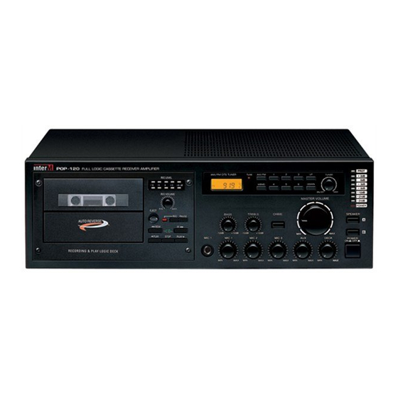
FRONT PANEL CONTROLS 22 21 POP-120 FULL LOGIC CASSETTE RECEIVER AMPLIFIER +2dB AM/FM DTS TUNER AM/FM TUNER -2dB MEMO DOWN -6dB -12dB ON/OFF -21dB MASTER VOLUME -24dB POWER BASS TRE BLE SPEAKER EJECT RE C PAUSE CHIME -12dB +12dB -12dB +12dB PLAY STOP... - Page 4 12. FORWARD PLAY BUTTON( )/REVERSE PLAY BUTTON( :Press this button, and tape will be in forward play mode. The indicator , lights up. :Press this button, and tape will be in reverse play mode. The indicator , lights up. 13. STOP BUTTON( Press this button to stop the tape.
- Page 5 26. SPEAKER SELECTOR These switches are used for connecting the output of amplifier to the speakers individually or totally. 27. OUTPUT LEVEL DISPLAY This display indicates the output level (RMS) per 0dB.
-
Page 6: Rear Panel Controls
This fuse holder contain AC fuse. When they are blown out replace them with same type fuse as following page. If they continuously blow, stop replacing fuse and refer servicing to qualified personnel. POP-120 POP-60 MODEL POP-30 VOLTAGE AC 115V/230V AC 115V/230V AC 115V/230V FUSE RATING 1.5A/250V/0.75A/250V... - Page 7 These terminals are for the connecting the speakers. Select the terminals of 4Ω or high impedance not to over load. 11. IMPEDANCE SELECTOR SWITCH This switch is for selecting the impedance of the high impedance terminal on speaker terminal MODEL POP-120 POP-30 POP-60 Voltage/Impedance 166Ω 83Ω 100V 333Ω...
-
Page 8: Maintenance
MAINTENANCE CLEANING OF HEADS AND TAPE PATH Generally, it is sufficient to clean heads after every 10 hours of operation. However, all surfaces over which tape travels should be cleaned before making high quality recordings. 1. Set the POWER switch to OFF and remove cassette door lid by pushing it up and then taking it out toward the front side after opening the door. - Page 9 4. Replace the door lid. Do not insert cassette until the cleaner dries out. DEMAGNETIZING HEADS Residual magnetism will gradually build up on the heads through continuous use and cause erasure of high frequencies and hiss. The heads and metallic parts of the tape path should be demagnetized after 20-30 hours of operation with a commercially available head demagnetizer.
- Page 10 NOTE ON CASSETTE TO PROTECT RECORDING FROM ACCIDENTAL ERASURE Remove the tab as illustrated so that the REC cannot be activated. To record on a cassette after tabs have been removed, simply cover the slot with cellophane or vinyl tape. To protect side A recording Do not stick and other material on the portion marked...
- Page 11 CONNECTION OF THE ANTENNA AND THE EARTHING CABLE FM RECEIVING ANTENNA The electric wave of FM broadcasting is weakening in hills and valleys, around buildings and in iron-re- inforced buildings because of its own nature. INSTALLATION OF AN ANTENNA EXCLUSIVELY FOR FM Connect the feeder of the antenna of the terminal of 300Ω...
- Page 12 ON EARTHING(EARTH GND) Broadcasting may de heard well without earth connection. But connect the earth to the earth terminal (GND) for safety and prevention of noise(Fig. 2). ANTENNA FM75W 300W EARTH (FIGURE 2)
-
Page 13: Installation Of The Speaker
INSTALLATION OF THE SPEAKER When you connect the speaker, remove the power cord from power outlet. And use the suitable termin- als connecting way as belows. FOR 4W TERMINAL SPEAKER FOR HIGH IMPEDANCE TERMINAL IMPEDANCE SECECTOR 100V (83W ) (4W ) Matching Matching Trans... -
Page 14: Specifications
Line in ............................1V/10KΩ • Frequency Response ......................80Hz~20000Hz • T.H.D (at 1KHz Rated Output) ....................Less than 1% • S/N ...............................90dB • Tone Control(100Hz~10KHz) ......................12dB • Speaker Output/Impedance ........POP-30:30W(11V/4Ω, 25V/21Ω,70V/63Ω,100V/333) POP-60:60W(15.5V/4Ω, 25V/10.5Ω,70V/82Ω,100V/166) POP-120:120W(22V/4Ω, 25V/5.2Ω,70V/40Ω,100V/83) • Line Out/Impedance........................1V/600Ω TUNER SECTION • Tuning Range ........................FM:87.5-108MHz .............................AM:522-1620KHz... - Page 15 MADE IN KOREA...
Need help?
Do you have a question about the POP-30 and is the answer not in the manual?
Questions and answers