Table of Contents
Advertisement
Advertisement
Table of Contents

Summary of Contents for Inter-m P-2000
-
Page 1: Power Amplifier
P-2000/P-3200 Power Amplifier Copyright 2004 Inter-M Corporation... -
Page 2: Table Of Contents
Welcome ... 3 Unpacking ... 3 Warnings ... 3 Operation... 5 Power Amplifier ... 6 Features ... 6 Front Panel Controls... 7 Operational Modes ... 11 Speaker Impedance and Connections ... 11 Speaker Connection Procedures... 12 Speaker Cable ... 13 Maintaining Proper Polarity ... -
Page 3: Welcome
A personal welcome to you from the management and employees of Inter-M Thank you for purchasing this fine Inter-M product. All of us here at Inter-M are dedicated to providing you with the highest quality products and the best value. - Page 4 P-2000/P-3200 Power Amplifier 8. Do not install near any heat sources such as radiators, heat registers, stoves, or other devices (including amplifiers) that produce heat. 9. Do not defeat the safety purpose of the polarized or grounding type plug. A polarized plug has two blades, with one wider than the other.
-
Page 5: Operation
P-2000/P-3200 Power Amplifier Operation Make certain that speakers and input sources are properly connected before switching Keep volume levels at minimum gain before switching on. NOTE: The system’s operation is delayed by approximately three seconds after pressing the AC Mains power switch. This is due to the built-in protection circuitry, designed to... -
Page 6: Power Amplifier
P-2000/P-3200 Power Amplifier Features Dual Power Supply • Individual power supplies for Left and Right channels for true dependability. Advanced Protection Circuitry • Thermal and current overload protection, short and open circuit protection, ultrasonic and RF protection circuitry for component and loudspeaker protection. -
Page 7: Front Panel Controls
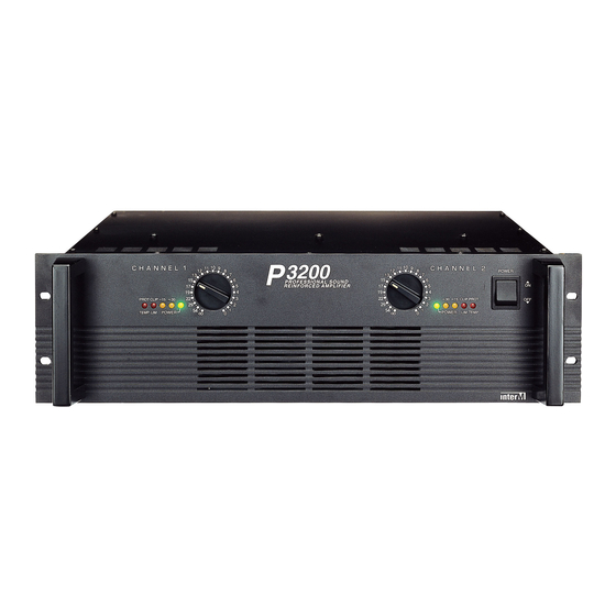
Front Panel Controls 1. Power Switch Pushing this switch up switches the unit on. Pushing it down switches the unit off. 2. Power Indicator LED When the unit is powered on, the Power LED will glow steadily. 3. Input Attenuators These are detented controls for regulating each channel’s input level. - Page 8 P-2000/P-3200 Power Amplifier Full Short Protection: Full output current peak of up to 25 amperes (50 amperes at 120VAC) is permitted, but if the output is shorted the current is reduced to approximately 25% of normal output. Compressor/Limiting: When maximum output power is reached, output level will be reduced to avoid distortion.
-
Page 9: Rear Panel Controls
Rear Panel Controls 1. AC Input Connect this cable to a standard AC outlet. 2. Input and Link Output Connectors Balanced input connectors are provided on hybrid XLR/TRS jacks. Link output connectors are provided on three-pin XLR connectors, and are used to operate multiple amplifiers in parallel mode. - Page 10 P-2000/P-3200 Power Amplifier Speakers may be connected in Stereo or Bridged Mono mode. Please refer to the illustrations below.
-
Page 11: Operational Modes
In Bridged Mono mode, both amplifier channels are bridged together and function as a single-channel amplifier. Only the Left channel input is active, and only the Left channel Input Attenuator controls the amp’s output. In this mode, minimum speaker impedance per channel is 8Ω. -
Page 12: Speaker Connection Procedures
Make certain the wires do not protrude from the terminals and touch the amplifier’s chassis, or an adjacent terminal. The P-2000/3200 is capable of very high output levels. Be certain to use a speaker system that can accept high input levels. If the input capacity of your speaker system is less than the amplifier’s rated output, you may protect your speakers by connecting a fuse... -
Page 13: Speaker Cable
P-2000/P-3200 Power Amplifier Speaker Cable Always use the heaviest-duty (lowest gauge) speaker cable available. The terminals can accommodate very thick speaker cable. Maintaining Proper Polarity It is very important to wire your speaker connectors consistently at each end of each cable, in order to maintain proper polarity. -
Page 14: Block Diagram
P-2000/P-3200 Power Amplifier Block Diagram... -
Page 15: Specifications
Stereo 4Ω (per channel) Stereo 2Ω (per channel) Bridged Mono 8Ω Bridged Mono 4Ω Frequency Response ( ± 0.5dB) Input Sensitivity T.H.D Damping Factor Output Circuit P-3200 P-2000 GENERAL Power Source Power Consumption P-3200 P-2000 Weight P-3200 P-2000 Dimensions Specifications and design subject to change without notice for improvements. - Page 16 Korea and China, and sales and marketing operations located in Japan, Europe, and the U.S.A. With more than 850 employees around the globe, Inter-M is well-poised for further growth and expansion.


Need help?
Do you have a question about the P-2000 and is the answer not in the manual?
Questions and answers