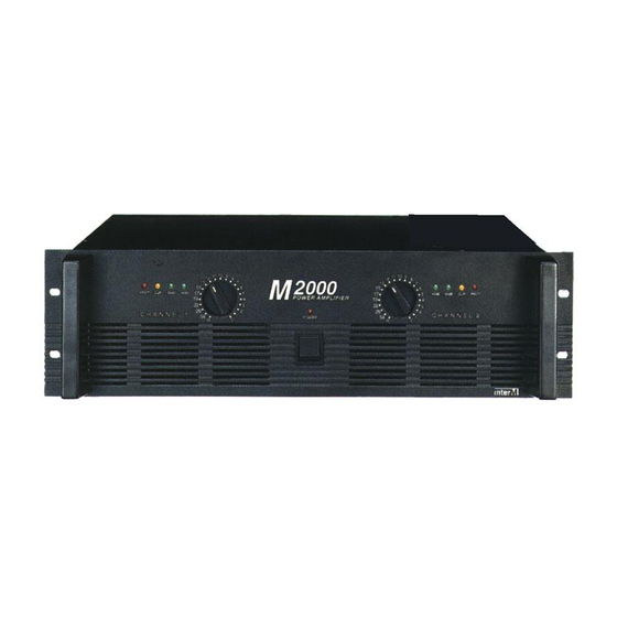
Summary of Contents for Inter-m M-1500
- Page 1 M-1500/2000 Power Amplifier 2000 POWER AMPLIFIER POWER...
-
Page 2: Table Of Contents
12. Positioning the Housed Amplifier ..................12 13. Troubleshooting .........................12 14. Block Diagram........................13 15. Specifications........................14 OFFICE : 226-9 DUGJUNG - LI, HOE CHUN - EUB, YANGJU - KUN, KYUNGKI - DO, KOREA TEL : 82-351-860-7041~5, FAX : 82-351-858-1907 Home Page : http://www.inter-m.co.kr E-mail : export@inter-m.co.kr... -
Page 3: Unpacking And Installation
To prevent fire or shock hazard, do not lames peuvent étre insérées à fond sans en laisser expose the unit to rain or moisture. aucune partie à découvert. M-1500/2000... -
Page 4: Features
Combination input connectors for each channel accommodate both balanced XLR or balanced 1/4” TRS plugs, as well as both Speakon and banana jack output connectors for maximum flexibility. - TRANSFORMER Toroidal transformer power supply for high current and low profile. M-1500/2000... -
Page 5: Front Panel Controls
5. POWER SWITCH AND INDICATOR The power switch is used to turn on and off the AC main power. The power indicator lights up when the amplifier is powered ON. 6. HANDLES You can handle this amplifier easily by using these handles. M-1500/2000... -
Page 6: Rear Panel Controls
CH1 OR CH2 (4Ω ~ 8Ω) (4Ω ~ 8Ω) (4Ω ~ 8Ω) (4Ω ~ 8Ω) CH 2 CH 1 CH 2 CH 1 The minimum impedance for the connected speaker system is specified in “Speaker Impedance” on page 6. M-1500/2000... - Page 7 WARNING: Due to the extremely high power output of the M-1500/2000 when used in Bridged mode, be sure to use only loudspeakers sufficiently rated to handle the resultant wattage (in Bridged mode, these must be 8-ohm speakers).
-
Page 8: Protection Circuitry
To guard against this problem, make sure the M-1500/2000 receives adequate ventilation on all sides and that both the front and rear panels are unobstructed. - SEVERE OVERCURRENT CONDITIONS This occurs whenever the signal being input to the M-1500/2000 rises to a level above 20% THD (Total Harmonic Distortion). - SHORTED SPEAKER CABLES This will occur if, due to faulty wiring, the hot and ground signals being output by the M-1500/2000 short one another. -
Page 9: Bridged And Parallel Modes
1500 watt output into a single 8 ohm channel (in the case of the M-1500) or a true 2000 watt output into a single 8 ohm channel (in the case of the M-2000). -
Page 10: Connections
POWER AMPLIFIER Connections Connections STEREO MODE BRIDGED MODE PARALLEL MODE M-1500/2000... -
Page 11: Link Connectors
Speaker Impedance Speaker Impedance M-1500/2000 series amplifier has three operating modes: Stereo, Bridged and Parallel and allows you to connect multiple speaker systems in parallel. Therefore, the minimum speaker impedance various depend- ing on the combination of these speakers. Be sure that the speaker impedance falls below the specified impedance. -
Page 12: Caution For Speaker Connection
The output capacity of your amplifier is very high: 1000W+1000W (4Ω) in stereo and 2000W (8Ω) in monaural on the M-2000: 750W+750W (4Ω) in stereo and 1500W (8Ω) in monaural on the M-1500. Be sure to use a speaker system that has sufficient input capacity. -
Page 13: Portable Rack Mounting
(8Ω~16Ω) (4Ω ~ 8Ω) (4Ω ~ 8Ω) BALANCED BALANCED 0dBm 0dBm ¥TIP=HOT ¥3=COLD BALANCED ¥RING=COLD BALANCED ¥2=HOT ¥SLEEVE=GND ¥1=GND (4Ω ~ 8Ω) (4Ω ~ 8Ω) CH 2 CH 1 CH 2 CH 1 230V 50Hz, 1300W BRIDGED PARALLEL STEREO M-1500/2000... -
Page 14: Positioning The Housed Amplifier
PROTECTION indicator lights. DC voltage of +/–2V Consult your dealer. The relay operates to or greater was generated protect the speaker in the power amplifier’s system. output circuit. M-1500/2000... -
Page 15: Block Diagram
POWER AMPLIFIER Block Diagram Block Diagram M-1500/2000... -
Page 16: Specifications
POWER AMPLIFIER Specifications Specifications M-1500 M-2000 Power Output Level f=1kHz, THD+N≤0.05% (Typical) STEREO RL=8Ω 500W+500W 670W+670W RL=4Ω 750W+750W 1000W+1000W BRIDGED RL=8Ω 1500W 2600W One Channel Driven f=1kHz THD+N≤0.05% RL=8Ω 500W 670W Frequency Response RL=8Ω, P.=1W 0dB+0.5, –1.5dB: f=DC~55kHz Power Bandwidth Half Power, THD+N≤0.1%... - Page 17 NOTE...
- Page 18 NOTE...
- Page 19 NOTE...
- Page 20 MADE IN KOREA 9007902810...


Need help?
Do you have a question about the M-1500 and is the answer not in the manual?
Questions and answers