Table of Contents
Advertisement
To the Installer:
Please attach these instructions
next to the water heater.
Installation and Operation Instructions Manual
WARNING: If the information in these instructions is not followed exactly, a
fire or explosion may result causing property damage, personal injury or death.
– Do not store or use gasoline or other flammable
vapors and liquids in the vicinity of this or any
other appliance.
– WHAT TO DO IF YOU SMELL GAS
• Do not try to light any appliance.
• Do not touch any electrical switch; do not use
any phone in your building.
!
WARNING
Improper installation, adjustment, alteration,
service or maintenance can cause serious injury or
property damage. Refer to this manual. For
assistance or additional information, consult a
qualified installer or service agency.
!
WARNING
Install in accordance with all local codes. In the
absence of local codes, refer to NFPA 54 or CSA
B149.1.
!
CAUTION
The recommended temperature for normal
residential use is 120°F. The dial on the aquastat
does not always reflect the out-coming water
temperature and it could occasionally exceed 120°F.
Variation in out-coming temperature could be
based on factors including but not limited to usage
patterns and type of installation. Test water at the
tap nearest to the water heater. See page 37 for
measuring the out- coming water temperature.
!
WARNING
Hotter water increases the risk of scald injury.
Before adjusting the water temperature setting,
read this instruction manual. Temperatures at
which injury occurs vary with the person's age and
the length of exposure. The slower reaction time of
children, elderly or physically or mentally
challenged persons increases the scalding hazard to
them. It is recommended that lower water tempera-
tures be used where these exposure hazards exist.
Households with small children or invalids may
require a temperature setting less than 120°F to
prevent accidental contact with hot water. To
produce less than 120°F, use point-of-use
temperature limiting devices.
#23402 EN
To the Consumer:
High Efficiency Commercial Gas Water Heater
Models: OT300, OT400, OT500
Warranty, Registration Card and Parts List are included.
Owner: Please remember to return the Registration Card!
– Installation and service must be performed by a
If higher water temperature is needed in part of the
water system, automatic temperature limiting
devices must be used on all lines to water taps.
Water heater blankets may restrict air flow to the
water heater and cause fire, asphyxiation, personal
injury or death.
Read all instructions thoroughly before attempting
installation or operation of your water heater. Keep
these instructions for future reference.
Local plumbing and electrical codes must be
followed in the installation of this water heater. In
the absence of a local code use the UNIFORM
PLUMBING CODE and the NFPA Code. Local codes
may supersede instructions in this installation
manual.
These instructions are a guide for the correct instal-
lation of the water heater. The manufacturer will
not be liable for damages caused by failure to
comply with the installation and operating instruc-
tions outlined on the following pages.
DO NOT use this appliance if any part has been
under water. Immediately call a qualified service
technician to inspect the appliance and to replace
any part of the control system and any gas control
which has been under water.
Please read these and all component
instructions and keep for future reference.
• Immediately call your gas supplier from a neigh-
bor's phone. Follow the gas supplier's instructions.
• If you cannot reach your gas supplier, call the fire
department.
qualified installer, service agency or the gas supplier.
!
WARNING
THIS MANUAL HAS BEEN PREPARED TO ACQUAINT
YOU WITH THE INSTALLATION, OPERATION, AND
MAINTENANCE OF YOUR WATER HEATER AND TO
PROVIDE IMPORTANT SAFETY INFORMATION.
FAILURE TO FOLLOW THESE INSTRUCTIONS OR ALL
APPLICABLE BUILDING CODES
AND REGULATIONS VOIDS THE WARRANTY ON
THIS WATER HEATER.
Rev2 9/2013
Advertisement
Table of Contents

Related Manuals for Bock Water heaters OT300


Summary of Contents for Bock Water heaters OT300
- Page 1 Installation and Operation Instructions Manual High Efficiency Commercial Gas Water Heater Models: OT300, OT400, OT500 Warranty, Registration Card and Parts List are included. Owner: Please remember to return the Registration Card! WARNING: If the information in these instructions is not followed exactly, a fire or explosion may result causing property damage, personal injury or death.
-
Page 2: Important Safety Instructions
IMPORTANT SAFETY INSTRUCTIONS The proper installation, use and servicing of this water heater is very important to your safety and the safety of others. This is the safety alert symbol. Statements following this symbol contain important safety information. Obey all safety messages that follow this symbol to avoid possible injury or death. -
Page 3: Table Of Contents
TABLE OF CONTENTS Section I: Specifications ..........4 Section II: General Information. -
Page 4: Section I: Specifications
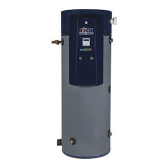
SECTION I: SPECIFICATIONS Figure 1: All Models Table 1: Dimensions CONNECTION SIZES DIMENSIONS, INCHES (cm) Model 119 300,000135,000 95 78.50 32.00 62.78 11.43 9.43 61.43 74.00 2" 2" 1-1/2" 4" 4" 1200 OT300N (450) (87.9) (39.6) (1,295) (1,627) (199) (81) (159) (29) (24) -
Page 5: Section Ii: General Information
SECTION II: GENERAL INFORMATION WHEN YOU RECEIVE YOUR NEW WATER HEATER Check the new equipment to see if all components are in good condition. If damage is observed or parts appear to be missing, contact your wholesaler. WATER TREATMENT/FILTRATION In areas where poor water conditions are suspected (i.e. lime, iron, and other minerals), it is essential that the water be tested and appropriate action taken to prevent damage to the water heater and ensure the quality of the water. - Page 6 SECTION II: GENERAL INFORMATION ANODE RODS The water heater is supplied with a factory installed powered anode system to prevent corrosion of internal tank components. Specifically, the type of anode system that is used is an impressed- current anode system. This system uses a power supply that regulates the protective current output based on actual conditions inside the tank.
- Page 7 SECTION II: GENERAL INFORMATION BACKFLOW PREVENTER (CLOSED SYSTEM) Some local municipal codes and ordinances require the use of these devices on potable (domestic) water lines. Where backflow preventers, check valves, or pressure regulating valves are required, it will be necessary to install a thermal expansion tank (designed for use with potable water) in order to prevent pressure build up in the water heater and associated piping, which could cause the T&P valve to discharge.
- Page 8 SECTION II: GENERAL INFORMATION SEISMIC RESTRAINT Regions of the United States and Canada that are considered earthquake zones require that the water heater(s) is properly braced to avoid movement or falling during a seismic event. Bock recommends a frame and strap system similar to the design shown in Figure 2. Use heavy gauge metal framing and anchor post bases to the floor.
-
Page 9: Section Iii: Pre-Installation
SECTION III: PRE-INSTALLATION LOCATION CAUTION This water heater must be located in an area where leakage of the tank, water line connections, or the temperature and pressure relief valve will not result in damage to the area adjacent to the water heater or to lower floors of the structure. When such location cannot be avoided, a suitable drain pan must be installed under the water heater. - Page 10 4,100 3,800 3,500 At minimum, use 1-1/4" gas supply pipe for models OT300 and OT400. For model OT500, use a minimum of 1-1/2" pipe. Maximum Gas Supply Pressure The gas supply pressure shall never be greater than 14" W.C. Pressures greater than 14" W.C. may damage the gas control which could cause a fire or explosion.
- Page 11 SECTION III: PRE-INSTALLATION COMBUSTION AND VENTILATION AIR The water heater can be installed to utilize combustion air from either inside or outside the building. Refer to "Section IV: Installation" for detailed venting specifications. If indoor air is used for combustion air it is imperative that the room has an adequate air supply. Inadequate air supplies may lead to unsafe levels of carbon monoxide (CO) and excessive levels of soot.
-
Page 12: Section Iv: Installation
SECTION IV: INSTALLATION VENT & COMBUSTION AIR INTAKE DANGER Failure to properly install the vent and combustion air intake system as outlined in this manual can result in unsafe operation of the water heater. To avoid the risk of fire, explosion, or asphyxiation from carbon monoxide, never operate this water heater unless it is properly vented and has adequate air supply for combustion. - Page 13 • PVC (Schedule 40 DWV, ASTM D2665) • CPVC (Schedule 40, ASTM F438) • ABS (Schedule 40 DWV, ASTM D2661) Please contact Bock Water Heaters for questions regarding materials that are not listed above. NOTICE Installations in Canada must conform to the requirements of CSA B149 code. Plastic vent systems must be assembled with pipe, fittings, cements, and primers listed to ULC S636.
- Page 14 (ft) † † Direct Vent NAT or OT300, OT400, OT500 Power Vent Equivalent length is measured between the 4" pipe connection on the water heater and the required 90° elbow termination fitting. Equivalent length is measured after the point of connection to the condensate assembly and includes the termination fitting (if used).
- Page 15 SECTION IV: INSTALLATION The vent and combustion air intake systems must be sufficiently supported along vertical and horizontal sections. At minimum, it is recommended that a support is placed along the vent or air intake piping every 4 feet. For horizontal systems, the first support shall be located immediately adjacent to the first 90-deg.
- Page 16 SECTION IV: INSTALLATION After the assembly is properly mounted to the exhaust pipe, apply more silicone caulk between the PVC fitting and metal exhaust pipe. Caulk all the way around the pipe. If a proper seal is not made, combustion gas will leak into the room and condensate will collect on the floor.
- Page 17 SECTION IV: INSTALLATION Horizontal Venting, Direct Vent 2-pipe termination This water heater may be vented horizontally (through a sidewall) with a two-pipe termination. Two holes through an exterior wall are required for the vent and combustion air intake pipes. Minimum clearances between the terminals must be met as specified in Figure 9.
- Page 18 SECTION IV: INSTALLATION Table 8: Direct Vent Terminal Clearances Canadian Installations US Installations A = Clearance above grade, veranda, 12 inches (30 cm) 12 inches (30 cm) porch, deck, or balcony B = Clearance to window or door that 36 inches (91 cm) 12 inches (30 cm) may be opened C = Clearance to permanently closed...
- Page 19 SECTION IV: INSTALLATION Install piping through the wall as shown in Figure 9. Adequate length of pipe must protrude beyond the exterior wall for attachment of the termination fitting. The recommended distance between the terminal fitting and the exterior wall is 1 in. (2.5 cm). Directions for cementing joints (such as the terminal fittings to the straight pipe) can be found on page 25.
- Page 20 SECTION IV: INSTALLATION Horizontal Venting, Power Vent 1-pipe termination This water heater may be vented horizontally (through a sidewall) with a one-pipe termination. In this case, the water heater will be utilizing air from inside the building for combustion air. A single hole through the exterior of the building is required for the vent pipe.
- Page 21 SECTION IV: INSTALLATION Table 9: Power Vent Terminal Clearances Canadian Installations US Installations A = Clearance above grade, veranda, 12 inches (30 cm) 12 inches (30 cm) porch, deck, or balcony 4 feet (1.2 m) below or to side B = Clearance to window or door that 36 inches (91 cm) of opening;...
- Page 22 SECTION IV: INSTALLATION Install piping through the wall as shown in Figure 12. Adequate length of pipe must protrude beyond the exterior wall for attachment of the termination fitting. The recommended distance between the terminal fitting and the exterior wall is 1 in. (2.5 cm). Directions for cementing joints (such as the terminal fittings to the straight pipe) can be found on page 25.
- Page 23 SECTION IV: INSTALLATION Vertical Venting, Direct Vent 2-pipe termination This water heater may be vented vertically (through a roof) with a two-pipe termination. Two holes through the roof are required for the vent and combustion air intake pipes. All clearances must comply with local codes or the latest edition of NFPA 54/ANSI Z223.1 or CSA B149.
- Page 24 SECTION IV: INSTALLATION CAUTION Annular spaces around vent pipe wall penetrations shall be permanently sealed using approved materials to prevent entry of combustion products into the building. Figure 15: Vertical Direct Vent Arrangement Vertical Venting, Power Vent 1-pipe termination This water heater may be vented vertically (through a roof) with a one-pipe termination. In this case, the water heater will be utilizing air from inside the building for combustion air.
- Page 25 SECTION IV: INSTALLATION Vent Terminal Dim Y Dim Y Requirements 1) Minimum 12 in. (30 cm) above roof (US). Minimum 18 in. (46 cm) above roof (Canada). 2) Minimum 12 in. (30 cm) above Support anticipated snow level (US). Minimum Bracket 18 in.
- Page 26 SECTION IV: INSTALLATION Assembling Vent and Air Intake Joints WARNING Cements and primers are highly flammable. Assemble joints in an adequately ventilated area away from heat sources or open flames. Do not smoke. Read cautions and warnings on material containers. CAUTION DO NOT use cement that is lumpy or thick.
- Page 27 SECTION IV: INSTALLATION Figure 18: Optional Condensate Drain on Air Intake Piping • Tighten a 1/8" NPT stainless steel hose barb fitting into the hole in the PVC pipe. The hose barb should be adaptable to 1/4" ID plastic tubing. •...
-
Page 28: Water Connections
SECTION IV: INSTALLATION WATER CONNECTIONS CAUTION This water heater incorporates fittings that contain a nonmetallic lining. DO NOT apply heat to these fittings when making sweat connections to the heater. Sweat tubing to an adapter before securing adapter to any fittings on water heaters. ALL PIPING SHOULD CONFORM TO LOCAL CODES AND ORDINANCES. - Page 29 SECTION IV: INSTALLATION Figure 20: Piping Diagram One Unit Figure 21: Piping Diagram Two Units Page 29...
- Page 30 SECTION IV: INSTALLATION Figure 22: Piping Diagram Three Units Figure 23: Piping Diagram One Unit with Storage Tank Page 30...
- Page 31 SECTION IV: INSTALLATION WATER (POTABLE) HEATING AND SPACE HEATING CONNECTIONS If this heater is used for water (potable) heating and space heating, the following require- ments apply: - Piping and components to the water heater for the space heating application must be suitable for use with potable water.
-
Page 32: Gas Connections
Check the rating label on the front of the water heater and make sure the gas to be used matches the gas stated on the rating label. Consult your local gas company or Bock Water Heaters with any questions. A manual valve, union,... - Page 33 SECTION IV: INSTALLATION WIRING All electrical wiring and connections must be in accordance with local codes. In the absence of local codes, wiring must conform to the National Electric Code ANSI/NFPA No. 70 or the Canadian Electrical Code C22.1. This water heater must be electrically grounded. Electrical power should be supplied through a fused disconnect switch located near the water heater.
- Page 34 SECTION IV: INSTALLATION Figure 27: Schematic Wiring Diagram Page 34...
-
Page 35: Section V: Operation
SECTION V: OPERATION FOR YOUR SAFETY READ BEFORE OPERATING WARNING: If you do not follow these instructions exactly, a fire or explosion may result causing property damage, personal injury or loss of life. This appliance does not have a pilot. It is equipped If you cannot reach your gas supplier, call with an ignition device which automatically lights the fire department. - Page 36 SECTION V: OPERATION SEQUENCE OF OPERATION Figure 29 gives a step-by-step description of the sequence of 3$"45 # operations for this water heater. See Troubleshooting section of this manual for solutions to error codes. !"# / 0 . !"# !"# !"# !"# !"#...
- Page 37 SECTION V: OPERATION ADJUSTING THE CONTROLS The temperature setpoint has been adjusted to 120°F at the factory. Allow the water heater to warm up to the factory adjusted setpoint and wait until the main operating control has shut off gas to the burner. Wait 30 seconds following shut-off of gas, then adjust the setpoint to a higher temperature.
- Page 38 SECTION V: OPERATION Following adjustment of the setpoint to a higher temperature (see Figure 30), the main burner should relight. Next, adjust the setpoint to a lower temperature (i.e. back to 120° F) and the gas valve will close, extinguishing the burner flame. The thermostat should be adjusted to the minimum setting that will meet the hot water needs of the application.
-
Page 39: Section Vi: Maintenance
SECTION VI: MAINTENANCE NOTICE TO THE OWNER: If you are having a mechanical problem with your water heater, contact your service company or installer. The required maintenance schedule for this water heater is shown in Table 10. Further detail is Table 10: Maintenace Schedule given in this section for each component. - Page 40 SECTION VI: MAINTENANCE FLUSH THE TANK Elements in the water such as lime and iron may accumulate in the heater. Accumulation of these elements can keep your water heater from operating at peak efficiency and may lead to premature tank failure. It is recommended that the tank is drained and flushed thoroughly twice a year to prevent buildup.
- Page 41 SECTION VI: MAINTENANCE INSPECT THE VENTING SYSTEM AND BURNER The vent and combustion air intake system should be checked at least once a year for damage and blockage. Make sure all joints are secure and that the system is properly supported. Inspect the outdoor terminals to make sure they are free of obstructions.
- Page 42 SECTION VI: MAINTENANCE (cont.) Figure 32: Removing the blower for burner inspection With the blower disassembled from the burner assembly, lift the burner straight up and through the burner assembly mounting flange. Carefully set aside all gaskets when disassembling the burner assembly. The gaskets must be used when reassembling. Inspect the inside of the burner for blockage.
-
Page 43: Section Vii: Troubleshooting
SECTION VII: TROUBLESHOOTING CAUTION For your safety, the repair and servicing of this equipment shall only be performed by a qualified agency. Table 12: General Troubleshooting Problem Possible causes Recommended Action 1) Check display for error code. 1) See Tables 12 and 13. 2) Contact qualified agency to purge the air Unable to light the burner 2) Air in the gas line. - Page 44 SECTION VII: TROUBLESHOOTING Table 13 shows a list of lockout error codes. A lockout code will be visible on the control display in the form of a code (letter "A" followed by a number) and a short message. Lockout errors require a manual reset to resume operation after the root cause of the problem has been solved.
- Page 45 SECTION VII: TROUBLESHOOTING Table 14 shows a list of blocking error codes. A blocking code will be visible on the control display in the form of a code (letter "E" followed by a number) and a short message. Blocking errors automatically reset once the error is corrected. Table 14: Blocking Error Codes BLOCKING ERRORS Description &...
- Page 46 SECTION VII: TROUBLESHOOTING Table 15 should be referenced when troubleshooting the powered anode system. If the status LED is off or flashing red, a problem has occurred and service is required. When the LED is a constant green, the system is operating properly. NOTICE: The tank must be filled with water prior to connecting the water heater to the power supply.
- Page 47 SECTION VII: TROUBLESHOOTING INSTALLER MENUS System and troubleshooting information such as fan speeds, flame signal, ignition attempts, and error history is available in the Installer Menu. Refer to Figure 33 for instructions to access this menu and useful tips. " "...
-
Page 48: Section Viii: Parts List
SECTION VIII: PARTS LIST Figure 34: optiTHERM Parts Table 16: optiTHERM Parts Description Description Control Panel Cover Power Supply Junction Box Knob Baffle Sight Glass Outlet Pipe Nipple Assembly Flame Rod Tank Temperature Sensors (2-in-1) Flame Rod Gasket T&P Relief Valve Hot Surface Ignitor Condensate Elbow Assembly Hot Surface Ignitor Gasket... - Page 49 SECTION VIII: PARTS LIST Figure 35: optiTHERM Control Panel Parts Table 17: optiTHERM Control Panel Parts Description Description Control Display Fuse, 5A (delay) Display Bracket Transformer (120 VAC / 24 VAC) Main Operating Control Powered Anode Status LED Terminal Block Powered Anode Power Supply Relay Standoff, 2.5 in.
- Page 50 SECTION VIII: PARTS LIST Figure 36: optiTHERM Burner Assembly Parts Table 18: optiTHERM Burner Assembly Parts Description Description Gas Pressure Switch Blower Gas Control Flange (w/ gasket) Gasket (blower to transition tube) Gas Control (NAT GAS_0-2,000 FT ALT) Transition Tube Gas Control (LP GAS_0-7,800 FT ALT;...
- Page 51 SECTION VIII: PARTS LIST Table 19: optiTHERM Wiring Harnesses Connections Part # Description From 21650 Blower Power Supply & PWM Main Control (J9) & Fuse Block Blower (2 connections) 21652 Transformer & Flame Rod Main Control (J13) 24V Transformer & Flame Rod 21655 Tank Temperature Sensors &...
-
Page 52: Section Ix: Warranty
SECTION IX: WARRANTY LIMITED WARRANTY FOR GAS-FIRED WATER HEATER Bock Water Heaters, Inc. 110 S. Dickinson Street Madison, WI 53703 Phone: 608-257-2225 WHAT DOES THIS LIMITED WARRANTY COVER? This limited warranty applies only to the original consumer purchaser. General Defects and Malfunctions: This warranty covers defections and malfunctions in your new water heater for a period of one year from the original installation date. - Page 53 INDIRECT, AND WHETHER ARISING IN CONTACT OR TORT. Some states do not allow the exclusion of incidental or consequential damages, so the above exclusion may not apply to you. Bock Water Heaters, Inc. • 110 South Dickinson Street • Madison, WI 53703 Telephone 608 -257-2225 • Fax 608 -257-5304 www.bockwaterheaters.com...
Need help?
Do you have a question about the OT300 and is the answer not in the manual?
Questions and answers