Table of Contents
Advertisement
Quick Links
To the Installer:
Please read these instructions and deliver to
consumer when installation is complete.
Installation and Operation Instructions Manual
WARNING: If the information in these instructions is not followed exactly, a
fire or explosion may result causing property damage, personal injury or death.
– Do not store or use gasoline or other flammable
vapors and liquids in the vicinity of this or any
other appliance.
– WHAT TO DO IF YOU SMELL GAS
• Do not try to light any appliance.
• Do not touch any electrical switch; do not
use any phone in your building.
WARNING
Improper installation, adjustment, alteration,
service or maintenance can cause serious injury
or property damage. Refer to this manual. For
assistance or additional information, consult a
qualified installer or service agency.
WARNING
Install in accordance with all local codes. In the
absence of local codes, refer to NFPA 54
CAUTION
The recommended temperature for normal
residential use is 120°F. The dial on the aquastat
does not always reflect the out-coming water
temperature and it could occasionally exceed
120°F. Variation in out-coming temperature could
be based on factors including but not limited to
usage patterns and type of installation. Test water
at the tap nearest to the water heater. See page 37
for measuring the out- coming water temperature.
WARNING
Hotter water increases the risk of scald injury.
Before adjusting the water temperature setting,
read this instruction manual. Temperatures at
which injury occurs vary with the person's age
and the length of exposure. The slower reaction
time of children, elderly or physically or mentally
challenged persons increases the scalding hazard
to them. It is recommended that lower water
temperatures be used where these exposure hazards
exist. Households with small children or invalids
may require a temperature setting less than 120°F
to prevent accidental contact with hot water.
To produce less than 120°F, use point-of-use
temperature limiting devices.
23446
To the Consumer:
Please read these instructions and keep for future
reference.
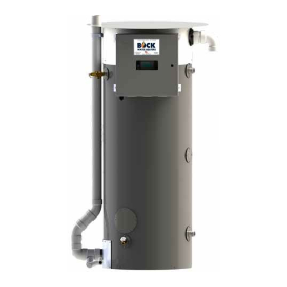
Outdoor Commercial Gas Water Heater
Models:
ODOT125, ODOT150, ODOT199
Warranty, Registration Card and Parts List are included.
Owner: Please remember to return the Registration Card!
• Immediately call your gas supplier from a neigh-
bor's phone. Follow the gas supplier's instructions.
• If you cannot reach your gas supplier, call the fire
department.
– Installation and service must be performed by a
qualified installer, service agency or the gas supplier.
If higher water temperature is needed in part of
the water system, automatic temperature limiting
devices must be used on all lines to water taps.
WARNING
Water heater blankets may restrict air flow to the
water heater and cause fire, asphyxiation, personal
injury or death.
Read all instructions thoroughly before attempting
installation or operation of your water heater. Keep
these instructions for future reference.
Local plumbing and electrical codes must be
followed in the installation of this water heater.
In the absence of a local code use the UNIFORM
PLUMBING CODE and the NFPA Code. Local codes
may supersede instructions in this installation
manual.
These instructions are a guide for the correct
installation of the water heater. The manufacturer
will not be liable for damages caused by failure to
comply with the installation and operating instruc-
tions outlined on the following pages.
FAILURE TO FOLLOW THESE INSTRUCTIONS OR
AND REGULATIONS VOIDS THE WARRANTY ON
THIS MANUAL HAS BEEN PREPARED TO
ACQUAINT YOU WITH THE INSTALLATION,
OPERATION, AND MAINTENANCE OF YOUR
WATER HEATER AND TO PROVIDE IMPORTANT
SAFETY INFORMATION.
ALL APPLICABLE BUILDING CODES
THIS WATER HEATER.
Rev3 4/21
Advertisement
Table of Contents

Related Manuals for Bock Water heaters ODOT125


Summary of Contents for Bock Water heaters ODOT125
- Page 1 Installation and Operation Instructions Manual Outdoor Commercial Gas Water Heater Models: ODOT125, ODOT150, ODOT199 Warranty, Registration Card and Parts List are included. Owner: Please remember to return the Registration Card! WARNING: If the information in these instructions is not followed exactly, a fire or explosion may result causing property damage, personal injury or death.
- Page 2 IMPORTANT SAFETY INSTRUCTIONS The proper installation, use and servicing of this water heater is very important to your safety and the safety of others. This is the safety alert symbol. Statements following this symbol contain important safety information. Obey all safety messages that follow this symbol to avoid possible injury or death.
-
Page 3: Table Of Contents
TABLE OF CONTENTS Section I: Specifications ..........4 Section II: General Information . -
Page 4: Section I: Specifications
SECTION I: SPECIFICATIONS Figure 1: All Models Table 1: Dimensions CONNECTION SIZES DIMENSIONS, INCHES (cm) Model 125,000 60,000... -
Page 5: Section Ii: General Information
SECTION II: GENERAL INFORMATION WHEN YOU RECEIVE YOUR NEW WATER HEATER Check the new equipment to see if all components are in good condition. If damage is observed or parts appear to be missing, contact your wholesaler. WATER TREATMENT/FILTRATION In areas where poor water conditions are suspected (i.e. lime, iron, and other minerals), it is essential that the water be tested and appropriate action taken to prevent damage to the water heater and ensure the quality of the water. - Page 6 SECTION II: GENERAL INFORMATION ANODE RODS The water heater is supplied with a factory installed powered anode system to prevent corrosion of internal tank components. Specifically, the type of anode system that is used is an impressed-cur- rent anode system. This system uses a power supply that regulates the protective current output based on actual conditions inside the tank.
- Page 7 SECTION II: GENERAL INFORMATION BACKFLOW PREVENTER (CLOSED SYSTEM) Some local municipal codes and ordinances require the use of these devices on potable (domestic) water lines. Where backflow preventers, check valves, or pressure regulating valves are required, it will be necessary to install a thermal expansion tank (designed for use with potable water) in order to prevent pressure build up in the water heater and associated piping, which could cause the T&P valve to discharge.
- Page 8 (standoffs) are located between the wall and the water heater. The standoffs may be field supplied or a kit may be purchased from Bock Water Heaters, Inc. One kit per water heater is required. Figure 3 shows the seismic strapping secured to an outside wall.
-
Page 9: Section Iii: Pre-Installation
SECTION III: PRE-INSTALLATION LOCATION WARNING This water heater must be installed outdoors and shall use the venting configuration as supplied by the manufacturer. All supplied parts, such as cover plates, doors, and the top pan must be properly installed for proper operation and to prevent a hazardous condition. - Page 10 combustion air. Avoid installations in corners where an eddy may develop. Eddies can lead to cross- the unit. Wind around the water heater allows combustion exhaust to be carried away and contamination of combustion air and lead to nuisance lockouts and increase maintenance on parts. provides fresh combustion air.
- Page 11 SECTION III: PRE-INSTALLATION LOCATION CAUTION Do not install this water heater under an overhang less than 3 ft (91.4 cm) from its top. The top of the water heater is defined as the highest point of the exhaust vent termination. The area under the overhang must be open on 3 sides.
- Page 12 SECTION III: PRE-INSTALLATION GAS SUPPLY LINE Prior to installation, contact your local gas utility to confirm that sufficient gas service is available for the water heater. The gas meter must have adequate capacity to supply the rated maximum gas input of the water heater in addition to other gas fired equipment connected to the meter. Minimum Gas Supply Pressure The gas supply must be capable of maintaining a minimum pressure at the inlet of the gas control during water heater operation at maximum input.
-
Page 13: Section Iv: Installation
SECTION IV: INSTALLATION VENT & COMBUSTION AIR INTAKE DANGER Failure to properly install the vent and combustion air intake system as outlined in this manual can result in unsafe operation of the water heater. To avoid the risk of fire, explosion, or asphyxiation from carbon monoxide, never operate this water heater unless it is properly vented and has adequate air supply for combustion. - Page 14 SECTION IV: INSTALLATION Condensate Trap Assembly Condensate Trap Assembly CONDENSATE TRAP AND DRAIN This heater comes with the exhaust vent factory installed. Before operation the condensate trap and drain This heater comes with the exhaust vent factory installed. Before operation the condensate trap and drain This heater comes with the exhaust vent factory installed.
- Page 15 SECTION IV: INSTALLATION WATER CONNECTIONS CAUTION This water heater incorporates fittings that contain a nonmetallic lining. DO NOT apply heat to these fittings when making sweat connections to the heater. Sweat tubing to an adapter before securing adapter to any fittings on water heaters. ALL PIPING SHOULD CONFORM TO LOCAL CODES AND ORDINANCES.
- Page 16 SECTION IV: INSTALLATION Figure 8: Piping Diagram One Unit Figure 9: Piping Diagram Two Units Page 16...
- Page 17 SECTION IV: INSTALLATION Figure 10: Piping Diagram Three Units Figure 11: Piping Diagram One Unit with Storage Tank Page 17...
- Page 18 Check the rating label on the front of the water heater and make sure the gas to be used matches the gas stated on the rating label. Consult your local gas company or Bock Water Heaters with any questions. A manual valve, union, and a sediment trap shall be provided in front of the gas valve.
- Page 19 SECTION IV: INSTALLATION WIRING All electrical wiring and connections must be in accordance with local codes. In the absence of local codes, wiring must conform to the National Electric Code ANSI/NFPA No. 70 or the Canadian Electrical Code C22.1. This water heater must be electrically grounded. Electrical power should be supplied through a fused disconnect switch located near the water heater.
- Page 20 SECTION IV: INSTALLATION Figure 14: Schematic Wiring Diagram Page 20...
-
Page 21: Section V: Operation
SECTION V: OPERATION FOR YOUR SAFETY READ BEFORE OPERATING WARNING: If you do not follow these instructions exactly, a fire or explosion may result causing property damage, personal injury or loss of life. This appliance does not have a pilot. It is equipped If you cannot reach your gas supplier, call with an ignition device which automatically lights the fire department. - Page 22 SECTION V: OPERATION SEQUENCE OF OPERATION Figure 16 gives a step-by-step description of the sequence of operations for this water heater. See Troubleshooting section of this manual for solutions to error codes. ...
- Page 23 SECTION V: OPERATION ADJUSTING THE CONTROLS The temperature setpoint has been adjusted to 120°F at the factory. Allow the water heater to warm up to the factory adjusted setpoint and wait until the main operating control has shut off gas to the burner. Wait 30 seconds following shut-off of gas, then adjust the setpoint to a higher temperature.
- Page 24 SECTION V: OPERATION Following adjustment of the setpoint to a higher temperature (see Figure 17), the main burner should relight. Next, adjust the setpoint to a lower temperature (i.e. back to 120° F) and the gas valve will close, extinguishing the burner flame. The thermostat should be adjusted to the minimum setting that will meet the hot water needs of the application.
-
Page 25: Section Vi: Maintenance
SECTION VI: MAINTENANCE NOTICE TO THE OWNER: If you are having a mechanical problem with your water heater, contact your service company or installer. The required maintenance schedule for this water heater is shown in Table 10. Further detail is given in this section for each component. Table 5: Maintenace Schedule WATER PIPING On an annual basis, all piping should be checked for leakage at joints, shut-off valves, and... - Page 26 SECTION VI: MAINTENANCE FLUSH THE TANK Elements in the water such as lime and iron may accumulate in the heater. Accumulation of these elements can keep your water heater from operating at peak efficiency and may lead to premature tank failure. It is recommended that the tank is drained and flushed thoroughly twice a year to prevent buildup.
- Page 27 SECTION VI: MAINTENANCE INSPECT THE VENTING SYSTEM AND BURNER The vent and combustion air intake system should be checked at least once a year for damage and blockage. Make sure all joints are secure and that the system is properly supported. Inspect the condensate elbow assembly for blockage every six months.
- Page 28 SECTION VI: MAINTENANCE Figure 19: Removing the blower for burner inspection With the blower disassembled from the burner assembly, lift the burner straight up and through the burner assembly mounting flange. IMPORTANT - Replacement gaskets must be used when reassembling (contact factory for gasket kit). Inspect the inside of the burner for blockage.
-
Page 29: Section Vii: Troubleshooting
SECTION VII: TROUBLESHOOTING CAUTION For your safety, the repair and servicing of this equipment shall only be performed by a qualified agency. Table 6: General Troubleshooting Problem Possible causes Recommended Action 1) Check display for error code. 1) See Tables 12 and 13. 2) Contact qualified agency to purge the air Unable to light the burner 2) Air in the gas line. - Page 30 SECTION VII: TROUBLESHOOTING Table 7 shows a list of lockout error codes. A lockout code will be visible on the control display in the form of a code (letter “A” followed by a number) and a short message. Lockout errors require a manual reset to resume operation after the root cause of the problem has been solved.
- Page 31 SECTION VII: TROUBLESHOOTING Table 8 shows a list of blocking error codes. A blocking code will be visible on the control display in the form of a code (letter “E” followed by a number) and a short message. Blocking errors automatically reset once the error is corrected. Table 8: Blocking Error Codes BLOCKING ERRORS Description &...
- Page 32 SECTION VII: TROUBLESHOOTING Table 9 should be referenced when troubleshooting the powered anode system. If the status LED is off or flashing red, a problem has occurred and service is required. When the LED is a constant green, the system is operating properly. NOTICE: The tank must be filled with water prior to connecting the water heater to the power supply.
- Page 33 SECTION VII: TROUBLESHOOTING INSTALLER MENUS System and troubleshooting information such as fan speeds, flame signal, ignition attempts, and error history is available in the Installer Menu. Refer to Figure 20 for instructions to access this menu and useful tips. Figure 20: Using the Installer Menu Page 33...
-
Page 34: Section Viii: Parts List
SECTION VIII: PARTS LIST Figure 21: optiTHERM Parts Table 10: optiTHERM Parts Page 34... - Page 35 SECTION VIII: PARTS LIST Figure 22: optiTHERM Control Panel Parts Table 11: optiTHERM Control Panel Parts SECTION A-A SCALE 1 : 4 Page 35...
- Page 36 SECTION VIII: PARTS LIST Figure 23: optiTHERM Burner Assembly Parts Table 12: optiTHERM Burner Assembly Parts Descrip)on Descrip)on Gas Control Transi)on Tube O-ring w/o Orifice (NAT GAS models) Gasket (transi)on tube to burner) O-ring w/ Orifice (LP GAS models) Burner Blower Gasket (burner to moun)ng flange) Gasket (blower to transi)on tube) Flange Assembly** ** - includes moun)ng flange, insula)on disk, retaining plate and bolts...
- Page 37 SECTION VIII: PARTS LIST Table 18: optiTHERM Wiring Harnesses Table 13: optiTHERM Wiring Harnesses Connections Part # Description From 21650 Blower Power Supply & PWM Main Control (J9) & Fuse Block Blower (2 connections) 21652 Transformer & Flame Rod Main Control (J13) 24V Transformer & Flame Rod 21655 Tank Temperature Sensor, Display, Flue Pass 2 Sensor Main Control (J5) Tank Temp. Sensors, Display , Flue Pass 2 Sensor , Harness #21671 21657 Hot Surface Ignitor Main Control (J4)
-
Page 38: Section Ix: Warranty
SECTION IX: WARRANTY LIMITED WARRANTY FOR GAS-FIRED WATER HEATER Bock Water Heaters, Inc. 110 S. Dickinson Street Madison, WI 53703 Phone: 608-257-2225 WHAT DOES THIS LIMITED WARRANTY COVER? This limited warranty applies only to the original consumer purchaser. General Defects and Malfunctions: This warranty covers defections and malfunctions in your new water heater for a period of one year from the original installation date. - Page 39 INDIRECT, AND WHETHER ARISING IN CONTACT OR TORT. Some states do not allow the exclusion of incidental or consequential damages, so the above exclusion may not apply to you. Bock Water Heaters, Inc. • 110 South Dickinson Street • Madison, WI 53703 Telephone 608-257-2225 • Fax 608-257-5304 www.bockwaterheaters.com...
- Page 40 Page 40...
Need help?
Do you have a question about the ODOT125 and is the answer not in the manual?
Questions and answers