Table of Contents
Advertisement
RTX810
Gigabit VPN Router
Instruction Manual
Thank you for purchasing the Yamaha RTX810.
Please carefully read this manual before use to ensure
appropriate installation and configuration.
Please be sure to follow all the warnings and precautions
provided in this manual to ensure appropriate and safe use.
Please retain this manual in a safe place for future reference.
Advertisement
Table of Contents

Related Manuals for Yamaha RTX810


Summary of Contents for Yamaha RTX810
- Page 1 RTX810 Gigabit VPN Router Instruction Manual Thank you for purchasing the Yamaha RTX810. Please carefully read this manual before use to ensure appropriate installation and configuration. Please be sure to follow all the warnings and precautions provided in this manual to ensure appropriate and safe use.
-
Page 2: Please Ensure To Read This First
Please ensure to read this first. Thank you very much for purchasing the Yamaha RTX810. This product is a Gigabit VPN Router that is suitable for use in small- and medium-sized enterprise networks. • LAN cable (x1) Please • Please ensure to read this first. -
Page 3: Table Of Contents
Table of contents Please ensure to read this first.........2 Chapter 3 Particular usage in this manual ........5 Connecting to the Safety precautions ............5 Internet Important notice ...............8 Concerning software license contracts when using the Selecting your Internet connection mode .....32 DOWNLOAD button ...........10 Permanently connecting to the Internet through a broadband line (PPPoE/CATV) ......33... - Page 4 Using in the IPv6 environment ........110 Q6: Unable to use USB device ........152 Changing the operation settings of UPnP function ..112 Q7: Other problems .............154 Controlling Yamaha switches ........115 Communication charges of the USB data communication terminal is abnormal ....155 Chapter 7 Initializing the product settings ........159...
-
Page 5: Particular Usage In This Manual
• Ensure not to process the cable in any way. March 2013). • Ensure not to use any staples to fix the cable in • Yamaha cannot accept any liability for any loss of or place. damage to information resulting from any use of the •... - Page 6 16. Ensure adequate heat ventilation. Failure to observe system. Please note that Yamaha cannot assume any this could result in fire or damage to the product. responsibility for any losses resulting from improper •...
- Page 7 (1) Delete the netvolante DNS registration. up. Please note that Yamaha cannot assume any (2) Initialize all the configurations. responsibility for any damage resulting from the loss or destruction of data during usage of the product.
-
Page 8: Important Notice
In addition, it is strongly recommended that you periodically check the Yamaha network peripheral equipment website (http://www.yamaha.com/products/en/network/) to obtain the latest information on the configurations and revisions of the product. -
Page 9: Open Source Software Used In The Product
Concerning trademarks • All the company and product names used in this manual are registered trademarks or trademarks of the companies concerned. • This product is equipped with RSA ® BSAFE™ software of RSA Security Inc. RC4 and BSAFE are the registered trademarks of RSA Security Inc. -
Page 10: Concerning Software License Contracts When Using The
“SOFTWARE”). Ensure not to change the setting to permit firmware revision YAMAHA grants you a personal non-exclusive license to use the update via the DOWNLOAD button if you do not agree with SOFTWARE only for purposes of running it on the PRODUCT. - Page 11 The Software is a “commercial item,” as that term is defined ARISING OUT OF THE SOFTWARE, USE THEREOF, at 48 C.F.R. 2.101 (Oct 1995), consisting of “commercial OR INABILITY TO USE THEREOF EVEN IF YAMAHA, computer software” and “commercial computer software YAMAHA'S SUBSIDIARIES AND AFFILIATES, THEIR documentation,”...
-
Page 12: What The Product Enables You To Do
Yamaha switches and power was turned off. collective VLAN settings both for the product and Yamaha switches are also available. Wide range of content available from the... -
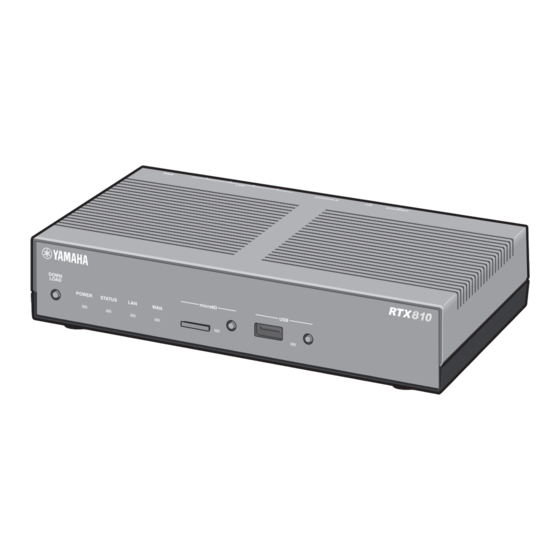
Page 13: Name And Function Of Individual Parts
Name and function of individual parts c microSD lamp/button/slot Front panel/Top panel Commercially available microSD cards can be used to copy the configuration file (pages 123 and 134), save the log file (page 133), and update the firmware (page 130). Before ejecting the microSD card, be sure to first cancel the connection by pressing and holding down the microSD button for two seconds. - Page 14 Name and function of individual parts (Continued from the previous page) Each lamp on the front panel indicates one of the three statuses ( Lit Flashing Off) POWER lamp The product is powered on. The product is starting up immediately after the power switch is turned on or shutting down immediately after the power switch is placed in STANDBY position.
-
Page 15: Rear Panel
Rear panel Bottom panel STANDBY CONSOLE LINK/DATA SPEED a Power cord Power cord and plug shape vary depending on the destination. b Power switch This switches the power status of the product to ON/ STANDBY. c Console port For use in connecting the RS-232C terminals (serial connector) of PCs when it is necessary to perform configurations from the console. -
Page 16: Flow Of Preparation Steps
Flow of preparation steps You must make preparations for using the product in this order: Make the necessary preparations for configuring network connections. Connecting a PC (or PCs) and your Preparation 1 broadband line to the product and ▶ Page powering it on ▼... -
Page 17: Ensure The Following Are Available Before Beginning
Ensure the following are available before beginning preparations LAN cables Provide LAN cables based on the number of PCs and distance. Up to four PCs can be directly connected to the LAN ports of the product. If you desire to connect five or more PCs, use a hub (a switch hub) that supports 10BASE-T, 100BASE-TX, or 1000BASE-T. -
Page 18: Preparation 1: Making Connections
Preparation 1 Making connections • To connect the product to the Internet through a USB data communication terminal, refer to “Connecting to the Internet using a USB data communication terminal” (page 49). STANDBY CONSOLE LINK/DATA SPEED Connect the LAN port of your PC to one of the LAN ports of the product with a LAN cable. - Page 19 W AN LA N C O N SO SP EE D AT A LI N K /D Plug the power cord of this product into an electrical outlet. Place the POWER switch in the ON position. The POWER lamp lights up after flashing several times. Power your PC or hub.
-
Page 20: Configuration Page
Preparation 2 Opening the “Basic configuration page” To change the configurations of the product, open the “Basic configuration page” using a Web browser on a PC connected to the product. Follow the steps below to open the “Basic configuration page”. Note •... - Page 21 Check that the product is powered on. Launch a web browser on your PC. Type “http://192.168.100.1/” in the address bar and then press Enter. The “Windows Security” screen appears. Leave the “User name” and “Password” fields blank, and click “OK”. The top page of the “Basic configuration page”...
-
Page 22: Preparation 3: Setting The Passwords
Preparation 3 Setting the passwords The factory default passwords are not set for the product. It is recommended that you set passwords to provide security measures. Once a password is set, anyone trying to access the product must enter it which makes it difficult for third parties to modify the configurations of the product. The product has two passwords: administration password and login password. - Page 23 Click Click Fill in Fill in Click...
- Page 24 Click “Advanced settings” on the top page of “Basic configuration page”. The “Advanced settings” screen appears. Click “Configure” to the right of “Configure users and access limits(HTTP, TELNET, SSH, SFTP)”. The “Configure users and access limits” screen appears. Type the password of the product in “Administration password”. Each password character entered is represented by a black dot.
- Page 25 Click Click Click Fill in Fill in Click...
- Page 26 Click “Advanced settings” on the top page of “Basic configuration page”. The “Advanced settings” screen appears. Click “Configure” to the right of “Configure users and access limits(HTTP, TELNET, SSH, SFTP)”. The “Configure users and access limits” screen appears. Click “Configure” to the right of “Nameless user”. The “Configure nameless user”...
-
Page 27: Preparation 4: Setting Date And Time
Preparation 4 Setting date and time In the “Configure machine” screen, configure the date and time for the product. Click Click Check Fill in Click Click... - Page 28 Click “Advanced settings” on the top page of “Basic configuration page”. The “Advanced settings” screen appears. Click “Configure” to the right of “Configure machine(Date/Time, buzzer)”. The “Configure machine” screen appears. Select “Change to the following date and time setting” under “Configure date and time”.
-
Page 29: Lan Side
Preparation 5 Configuring the IP address on the LAN side To connect LANs at different locations via broadband connections, make sure the network addresses for LANs do not overlap. Determine a new network address for each LAN and configure the IP address and netmask according to the new network address on the product and PC. - Page 30 Fill in Fill in Click Enter the IP address on the LAN side of the product in “LAN port IP address setup”. Primary IP address Enter the IP address according to the new network address you determined, and select the netmask. Enter the IP address you want to assign to a PC within the LAN in “DHCP server functions”.
-
Page 31: In Lan
Preparation 6 Changing the IP addresses of PCs in LAN If you change a LAN network address, you also need to change IP addresses and netmasks of PCs in the LAN. If you have devices other than PCs in the LAN, you also need to change their IP addresses and netmasks. -
Page 32: Selecting Your Internet Connection Mode
Selecting your Internet connection mode The product supports different Internet connection modes. Necessary broadband contract or a contract with an Internet service provider varies depending on the connection mode. Please read instructions regarding connection modes. Permanently connecting to the Internet through ▶... -
Page 33: A Broadband Line (Pppoe/Catv)
Connection 1 Permanently connecting to the Internet through a broadband line (PPPoE/CATV) Specify the destination in the “Basic configuration page” to connect to the Internet. If you use a network PPPoE connection or an unnumbered connection, refer to “Permanently connecting to the Internet using network connection service”... - Page 34 Checking the connection mode Click The line type is automatically detected. Click Click “Configure provider” on the top page of “Basic configuration page”. The broadband line auto-distinction function works to show the window for the connection mode selected for the connected line. Note Note that the broadband line auto-distinction process takes place only once.
- Page 35 Check the connection mode that is automatically determined and then click “Next”. Click “Next”. The setting screen corresponding to the connected line appears. The following configurations vary depending on the connected line. For details, refer to the description for the connection line you selected. If no line was chosen qFailed to automatically determine broadband line.
- Page 36 2 - Specifying your provider Terminal broadband connection over PPPoE information (from page 35) Fill in Fill in Fill in Click Enter the configuration name. Enter a descriptive destination name. It is a good idea to name the configuration so that you can easily identify it when it needs to be modified.
- Page 37 3 - Specifying the DNS server Terminal broadband connection over PPPoE address (from page 35) Specify Click Specify the DNS server address. If the DNS server address is not assigned by your provider: Click “Do not specify DNS server address and auto-retrieve from the provider” to select it. If the DNS server address is assigned by your provider: Click “The contract with the provider stipulates a DNS server address designation”...
- Page 38 4 - Checking the setting Terminal broadband connection over PPPoE information (from page 35) Check Click Ensure that the entries displayed on the screen comply with the information provided by your provider. If an incorrect setting has been made, click “Back” to bring up the necessary setting screen to set it correctly.
-
Page 39: Connecting To The Internet
5 - Connecting to the Internet Terminal broadband connection over PPPoE (from page 35) Click Check Click “Connect”. The product connects to the Internet and shows the “Connect/disconnect provider” screen. Click “Return to top” to return to the top page of the “Basic configuration page”. Check whether the product is connected to the Internet. - Page 40 2 - Specifying your provider Terminal broadband connection over DHCP (i.e. CATV Internet) information (from page 35) Fill in Specify Click Enter the configuration name. Enter a descriptive destination name. It is a good idea to name the configuration so that you can easily identify it when it needs to be modified.
- Page 41 3 - Specifying the DNS server Terminal broadband connection over DHCP (i.e. CATV Internet) address (from page 35) Specify Click Specify the DNS server address. If the DNS server address is not assigned by your provider: Click “Do not specify DNS server address and auto-retrieve from the provider” to select it. If the DNS server address is assigned by your provider: Click “The contract with the provider stipulates a DNS server address designation”...
- Page 42 4 - Confirming the entries before Terminal broadband connection over DHCP (i.e. CATV Internet) connecting to the Internet (from page 35) Check Click Check Ensure that the entries displayed on the screen comply with the information provided by your provider. If an incorrect setting has been made, click “Back”...
-
Page 43: Permanently Connecting To The Internet Using Network
Connection 2 Permanently connecting to the Internet using network connection service Specify the destination in the “Basic configuration page” to connect to the Internet. The following description also applies when you use unnumbered connections. If you use an ADSL connection service or a fiber optic Internet service that assigns only one IP address, refer to “Permanently connecting to the Internet through a broadband line (PPPoE/CATV)”... - Page 44 Specifying the connection mode Click Click Click “Advanced settings”. The “Advanced settings” screen appears. Click “Configure” to the right of “Detailed basic connection setting” The “Detailed basic connection setting” screen appears.
- Page 45 Click Click Click Click “Add”. The “Register provider” screen appears. Click the “Network broadband connection over PPPoE”. Click “Next”. The “Register provider” screen appears.
- Page 46 Specifying your provider information Fill in Fill in Fill in Enter the configuration name. Enter a descriptive destination name. It is a good idea to name the configuration so that you can easily identify it when it needs to be modified. Enter the user ID.
- Page 47 Specify Specify Specify the Network Address Translation (NAT) configuration. Dynamic address translation (NAT) Select a method for translating the line's address into a LAN address and vice versa. • Enable NAT: Select when translating a line's address and the LAN address on a one-to-one basis. •...
- Page 48 Connecting to the Internet Click Click Check Click “Submit”. The “Register provider” screen appears. Click “Return to top”. The product is automatically connected to the Internet. The screen returns to the top page of the “Basic configuration page”. Check whether the product is connected to the Internet. Check that the product is connected to the Internet by viewing the status of Internet connection on the lower part of the screen.
-
Page 49: Connecting To The Internet Using A Usb Data Communication Terminal
Connection 3 Connecting to the Internet using a USB data communication terminal The product can be connected to the Internet by connecting a commercially-available data communication terminal that supports USB ports to the USB port. Connect a USB data communication terminal to the product before specifying the destination in the “Basic configuration page”... - Page 50 (page 126) for beeps. USB data communication terminals that are known to work For a list of latest USB data communication terminals that are known to work, please http://www. yamaha.com/products/en/network/ and go to the product information page on RTX810.
- Page 51 Specifying the connection mode Click Click Click Click “Configure provider” on the top page of “Basic configuration page”. The “Configure provider 1/4” screen appears. Click “Mobile Internet connection”. Click “Next”. The “Configure provider 2/4” screen appears.
- Page 52 Specifying your provider information Fill in Fill in Fill in Fill in Fill in Specify Click Enter the configuration name. Enter a descriptive destination name. It is a good idea to name the configuration so that you can easily identify it when it needs to be modified. Enter the access point name.
- Page 53 Configure outgoing restrictions. Configure the outgoing restrictions based on the cumulative send/received data and the cumulative connection period. Depending on your contract plan, unusual billing can occur due to long connection times. Be sure to check your contract plan before configuring it. Click “Next”.
- Page 54 Specifying the DNS server address Specify Click Specify the DNS server address. If the DNS server address is not assigned by your provider: Click “Do not specify DNS server address and auto-retrieve from the provider” to select it. If the DNS server address is assigned by your provider: Click “The contract with the provider stipulates a DNS server address designation”...
- Page 55 Checking the setting information Check Click Ensure that the entries displayed on the screen comply with the information provided by your provider. If an incorrect setting has been made, click “Back” to bring up the necessary setting screen to set it correctly. Click “Submit”.
- Page 56 Connecting to the Internet Click Check Click “Connect”. The product connects to the Internet and shows the “Connect/disconnect provider” screen. Click “Return to top” to return to the top page of the “Basic configuration page”. Check whether the product is connected to the Internet. Check that the product is connected to the Internet by viewing the status of Internet connection on the lower part of the screen.
-
Page 57: (Ipsec Lan-To-Lan Connection)
Creating a Virtual Private Network (VPN) using IPsec (IPsec LAN-to-LAN connection) You can create a Virtual Private Network (VPN) to connect LANs if the product is connected to a broadband Internet connection. LAN-to-LAN connection using IPsec ensures secure connection via the Internet. A VPN can be created using conventional broadband connections such as ADSL. -
Page 58: Creating A Virtual Private Network (Vpn) Using Ipsec
Creating a Virtual Private Network (VPN) using IPsec (IPsec LAN-to-LAN connection) (continued from the previous page) IPsec that can be used with Note • Because IPsec tunnels are to be configured with the router the product connected to a broadband connection, it will be necessary to configure the broadband connections before setting up the •... - Page 59 IPsec has two communication modes. Before configuring the settings There are basically two types of modes in IPsec-based communications: tunnel mode and transport mode. These • To connect LANs, it will be necessary to configure two modes can be used in combination, but it is not possible a different network address for each LAN to avoid to doubly apply each mode.
- Page 60 Creating a Virtual Private Network (VPN) using IPsec (IPsec LAN-to-LAN connection) (continued from the previous page) Click “Add ” to the right of the destination you Configure the required settings and then click want to register. “Submit”. The connection destination is registered. For more details on the settings, click “Help”...
-
Page 61: Gaining Remote Access Using L2Tp/Ipsec
Gaining remote access using L2TP/ IPsec The product supports L2TP (Layer-2 Tunneling Protocol)/IPsec. If it is connected to a broadband connection, it works as a virtual private network (VPN), allowing users in remote locations (like on the road) to access to a PC on the LAN. IPsec VRN connections are more secure than PPTP. -
Page 62: Required Settings
Gaining remote access using L2TP/IPsec (Continued from the previous page) L2TP/IPsec that can be used Required settings with the product For remote access, a router, a PC or a smartphone needs to be configured as shown below. • The product supports data encryption for IPsec. •... - Page 63 Registering connection Select your desired authentication method destinations and then click “Next”. The “Register VPN connection setting” screen appears. Register connection destinations. • PP: Only the specified host name or IP address Note is allowed as the destination, and the user ID and •...
- Page 64 Gaining remote access using L2TP/IPsec (Continued from the previous page) Configuring a server or PC Configure the settings required and then click in the LAN “Submit”. The connection destination is registered. Remote access requires settings that provide you with access to the server or PCs in the LAN via TCP/IP protocol. For more details on the settings, click “Help”...
- Page 65 Gaining remote access via Tap on “Network”. Changing the settings for a device (such as a smartphone) that remotely accesses a PC Tap on “Settings”. Tap on “VPN”. Tap on “General”.
- Page 66 Now, the setting up of a remote access connection is Select “L2TP” and enter the necessary setup complete. information. Description Type “Yamaha-vpn” as the L2TP client name. Server Enter the host address obtained with the netvolante DNS service or the WAN IP address of the product. Account Enter the authentication user ID you set in Step 4 on page 64.
- Page 67 (such as a smartphone) that remotely Tap on “Network”. accesses a PC Tap on “VPN”. Press the Home icon, press “Menu” and tap Tap on “Yamaha-vpn” and slide “VPN” On. on “Settings”. VPN connection to the product now begins. Tap on “Wireless & networks”.
- Page 68 Tap on “Add L2TP/IPsec PSK VPN”. Tap on “Add VPN”. Enter necessary setup information. VPN name Type “Yamaha-vpn” as the L2TP client name. Set VPN server Enter the host address obtained with the netvolante DNS service or the WAN IP address of the product.
- Page 69 Tap on “Wireless & networks”. Tap on “VPN settings”. Enter the authentication user ID in “Username” Tap on “Yamaha-vpn”. and password in “Password” you set in Step 4 on page 64 and tap on “Connect”. VPN connection to the product now begins.
-
Page 70: Gaining Remote Access Using Pptp
Gaining remote access using PPTP The product supports PPTP (Point to Point Tunneling Protocol). If it is connected to a broadband connection, you can use it as a virtual private network (VPN) router to access to a PC on the LAN from a remote location. For remote access, register remote users' user IDs and passwords with the product and configure VPN connections on a remote PC. - Page 71 PPTP that can be used with Note • Because PPTP tunnels are to be configured with the router the product connected to a broadband connection, it will be necessary to configure the broadband connections before setting up remote • The product supports data encryption for PPTP. The RC4 access using PPTP.
- Page 72 Gaining remote access using PPTP (Continued from the previous page) Required settings Registering connection destinations For remote access, a router or a PC needs to be configured as shown below. Register connection destinations. Note • Up to ten users can be registered for PP connection. There Router settings are up to 50 PPTP tunnel connections at a time, including the ones used in anonymous connections.
- Page 73 Configuring a server or PC Select your desired authentication method in the LAN and then click “Next”. The “Register VPN connection setting” screen appears. Remote access requires settings that provide you with access to the server or PCs in the LAN via TCP/IP protocol. •...
- Page 74 Gaining remote access using PPTP (Continued from the previous page) Gaining remote access from In “Internet address”, enter the host address a PC that has Windows 7 obtained with the netvolante DNS service or the WAN IP address of the product. installed Type “VPN_PPTP”...
- Page 75 Accessing the product Click “Options” tab, and then click “PPP Settings”. Configure broadband connections and connect the product to the Internet. Select the check box as shown below and then click “OK”. Click “View network status and tasks” in “Control Panel”. Click “Connect to a network”.
- Page 76 Gaining remote access using PPTP (Continued from the previous page) Under “Authentication”, select “Allow these Enter the authentication user ID in “User protocols”, select the check boxes as shown name” and password in “Password” you set below and then click “OK”. in Step 4 on page 73 and click “Connect”.
- Page 77 Gaining remote access from In “Internet address”, enter the host address a PC that has Windows Vista obtained with the netvolante DNS service or installed the WAN IP address of the product. Type “VPN_PPTP” in “Destination name”. Changing the settings of a PC for remote accessing Click “View network status and tasks”...
- Page 78 Gaining remote access using PPTP (Continued from the previous page) Accessing the product Click “Options” tab, and then click “PPP Settings”. Configure broadband connections and connect the product to the Internet. Select the check box as shown below and then click “OK”. Click “View network status and tasks”...
- Page 79 Under “Logon security”, select “Allow these Enter the authentication user ID in “User protocols”, select the check box as shown name” and password in “Password” you set below and then click “OK”. in Step 4 on page 73 and click “Connect”. VPN connection to the product now begins.
- Page 80 Gaining remote access using PPTP (Continued from the previous page) Gaining remote access from Click “Create a new connection”. a PC that has Windows XP installed Changing the settings of a PC for remote accessing The “Welcome to the New Connection Wizard” will launch.
- Page 81 Select “Virtual Private Network connection” Enter the host address obtained with the and then click “Next”. netvolante DNS service or the WAN IP address of the product and then click “Next”. Type “VPN_PPTP” in “Company Name” and then click “Next”. Click “Finish”.
- Page 82 Gaining remote access using PPTP (Continued from the previous page) Accessing the product Select the encryption mode according to the setting you made in Step 4 on page 73. Configure broadband connections and connect the product to the Internet. • If “Non-encrypted access denied” is selected with the product: Select “Require encryption Double-click “VPN_PPTP”...
- Page 83 Click “Networking” tab, select “Automatic” for Click “Connect”. “Type of VPN” and then click “Settings”. Select the check box as shown below and then click “OK”. • Enable LCP extensions: Unchecked • Enable software compression: Unchecked VPN connection to the product now begins. •...
-
Page 84: (Pptp-Lan-To-Lan Connection)
Creating a Virtual Private Network (VPN) using PPTP (PPTP-LAN-to-LAN connection) You can create a Virtual Private Network (VPN) to connect LANs if the product is connected to a broadband Internet connection. LAN-to-LAN connection using PPTP ensures secure connection via the Internet. A VPN can be created using conventional broadband connections such as ADSL. - Page 85 PPTP that can be used with Note • Because PPTP tunnels are to be configured with the router the product connected to a broadband connection, it will be necessary to configure the broadband connections before setting up the • The product supports data encryption for PPTP. The RC4 LAN-to-LAN connection using PPTP.
-
Page 86: Creating A Virtual Private Network (Vpn) Using Pptp
PPTP server or client. Configure the RTX810 attached to the LAN on the connecting end as a PPTP client and the RTX810 attached to the LAN on the connected end as a PPTP server. On the top page of “Basic configuration page”, click “Advanced settings”, then click... - Page 87 Connecting with PPTP Connect to a PPTP server. Note • To connect to a PPTP server, the product for which you perform the following operation must be configured as a PPTP client. • The “Connect” and “Disconnect” buttons appear when the product is configured as a PPTP client.
-
Page 88: Linking Lans Together Through Ipip Tunnels Using A
Linking LANs together through IPIP tunnels using a closed network LAN-to-LAN connections via the Internet involve the risk of data wiretapping or tampering. Thus, it will be necessary to encrypt data. For a highly confidential network such as a closed network, the need for data encryption is reduced. Because of this IPIP tunnel connections assure data confidentiality. - Page 89 Before configuring the Configuring the product to settings connect to a closed network To connect the product to a closed network, configure the • To connect LANs, it will be necessary to configure required settings in the “Terminal broadband connection a different network address for each LAN to avoid over PPPoE”...
- Page 90 Linking LANs together through IPIP tunnels using a closed network (Continued from the previous page) Configuring the product to Enter necessary setup information. use IPIP tunnels Configuration name To use the product and destination equipment by connecting Enter a descriptive destination name. them with IPIP tunnels, configure the required settings in User ID the “LAN-to-LAN network over IPIP tunneling”...
- Page 91 Creating IPIP tunnel Enter necessary setup information. connections Configuration name Once the above configurations have been completed, IPIP Enter a descriptive destination name. tunnel communications are automatically established (no Destination IP address manual operations are required). Once the IPIP tunnel Enter the IP address assigned to the connection connections are complete, the top page of the “Basic configuration page”...
-
Page 92: Outline Of Unauthorized Accesses And Security
Outline of unauthorized accesses and security measures Intrusion from Internet Internet Invalid security hole packets Invalid packets Intrusion from security hole Computer virus Server What is unauthorized A particular attention is required if a global IP address is assigned to your access from the Internet? •... - Page 93 2. Intrusions exploiting security holes responsibility. of the operating system or server • Please note that Yamaha cannot accept any liability for any software losses or damage resulting from incorrect use. This type of unauthorized access can be prevented at a high rate by upgrading the operating system or server software, 1.
-
Page 94: Configuring The Filter Settings
Configuring the filter settings In the product, up to 100 filters can be set for each connection destination. Each filter can block packets depending on the packet transmission source or destination, the protocol type, or the direction. Invalid packets can be prevented from entering your LAN by setting impossible packets or packets that may be used for unauthorized accesses to be discarded when they pass the router. - Page 95 Features of the filter of the Filter number indication You can use almost unlimited filter function numbers of the product product. In “Basic configuration page”, up to 100 numbers (0 to 99) can be set for each destination. The following Static filter and dynamic filter shows the correspondence between areas and filter numbers used in “Basic configuration page”.
- Page 96 Configuring filter settings (Continued from the previous page) Registering a filter Select a default filter set (security level) In the product “Basic configuration page”, seven security The concept of filter settings intended levels are defined by combining filters. When you register a for security new provider, a security level is set automatically according We recommend that you configure filter settings based on...
- Page 97 CD-ROM) for examples of actual filter settings. For examples of more professional filter settings and the grammar, please refer to “Command reference” (included in the attached CD-ROM) or the Yamaha network peripheral equipment website (http://www.yamaha.com/products/en/network/). For more details on the settings, click “Help” on the setup screen and refer to the description displayed.
-
Page 98: Detecting Unauthorized Accesses And Warning
Detecting unauthorized accesses and warning about them The intrusion detection function detects intrusions and attacks from the Internet and warns you about them. It helps enhance security by configuring a filter that can block suspicious transmission sources and applications to based on the detected information. - Page 99 Configuring the intrusion Checking the history of detection function illegal access detection In the “Configure unauthorized access detection”, you can The history of illegal access detection can be checked in set the direction of packets to be detected and the processing the “Intrusion detection information”...
-
Page 100: Restrict Hosts That Can Change Product Settings
Restrict hosts that can change product settings The product is equipped with password function and host restricting function to assure the security of the product itself. Using those functions enables you to prevent third persons from changing a router setting without permission. The product can be accessed by means of the web browser (HTTP), TELNET, SSH, or SFTP software. - Page 101 Registering users logging in You can also restrict access from anonymous users the product Access restriction for using anonymous users can be defined You can register users on the “Add user” screen, and restrict by configuring the settings on the “Configure nameless users who can log in the product.
-
Page 102: Using A Service Requiring A Global Ip Address
Using a service requiring a global IP address within LAN When you attempt to use an application program that requires a global IP address from your LAN via the router, the program may not operate correctly. You can solve the problem using either of the following methods. 1. - Page 103 2. Using the DMZ host function to solve the problem When the product receives a packet sent to an address that is not registered in the NAT/IP masquerade table, the packet will be transferred to a host with a specific IP address. This setting is possible owing to the DMZ host function. Note •...
-
Page 104: Using The Netvolante Dns Service
Using the netvolante DNS service What is the netvolante DNS service? To construct a server to publish your website, or share a working file via the Internet, the global IP address of the server must be known. However, an assigned global IP address may be changed upon reconnection or after a certain time even if permanent connection to the Internet has been established. - Page 105 • Note that your desired host name is not always available. • Lookup of the obtained host address is possible, but reverse lookup is not possible. • The netvolante DNS service uses a Yamaha original protocol, and the obtained host address cannot be registered with external dynamic DNS servers.
-
Page 106: Publishing A Server
Publishing a server If you want to publish a server to the Internet, first assign a fixed private IP address to the server to be published, and register the IP address conversion table (Static IP masquerade). Then, configure a filter in the product to permit access from outside the LAN. -
Page 107: Conversion Table
Registering the IP address Changing settings to permit conversion table access On the “Register static IP masquerade” screen, register the To permit access to the server, configure a filter intended conversion table of protocol, port number and the server for the server IP address and communication protocol. The IP address (Static IP masquerade settings). -
Page 108: Using Mail Notification
Router data flow out to the Internet without being encrypted. Please exercise care not to do so. Router Router Mail server Relatively safe password flow Risk of information leak RTX810 Risky password flow... - Page 109 Registering a mail server Notifying of illegal access used for mail notification detection by e-mail On the “Configure mail server” screen, register a mail server The record of unauthorized accesses detected by firewall used for sending e-mail to the notification destination. (page 92) of the product can be sent to the specified e-mail address periodically.
-
Page 110: Using In The Ipv6 Environment
Using in the IPv6 environment The product supports “IPv6” (Internet Protocol Version 6), Introducing IPv6 into PCs an internet protocol of the next generation. As IPv6 inherits functions related to traditional “IPv4”, you can use the new protocol without affecting the existing network. Introduce IPv6 in a Windows 7 or Windows Vista environment Note... - Page 111 Configuring the product to Checking the IPv6 use IPv6 connection Before beginning configuration, register the connection Take the following steps to check whether the IPv6 destination (provider) using IPv6 on the “Configure IPv6” environment has been correctly configured. screen. Note The product and a PC can be communicated with each other once If the provider is not registered, your IPv6 connecting operation they are connected with a LAN cable.
-
Page 112: Changing The Operation Settings Of Upnp Function
Changing the operation settings of UPnP function What is UPnP function? Configuring the setting to use UPnP function UPnP is the acronym of Universal Plug and Play, a mechanism where the UPnP-supported operating system The UPnP function of the product is set to “Do not use” automatically detects UPnP-supported devices in the by factory default. -
Page 113: For Windows Vista
Checking whether your PC For Windows Vista can use the UPnP function Click the “Start” button, then click “Control Panel”. Take the following steps to check whether your PC can use the UPnP function. From “Network and Internet”, click “View network status and tasks”. - Page 114 Changing the operation settings of UPnP function (Continued from the previous page) For Windows XP Click the “Start” button, then click “Control Panel”. Click “Add or Remove Programs”. Click “Add/Remove Windows Components” on the left of the screen. Click “Networking Services”, then click “Details”.
-
Page 115: Controlling Yamaha Switches
From the setup screen of the product, you can change Click “Submit”, then click “Return to top”. settings or check the status of Yamaha switches. To change settings or check the status of Yamaha switches, On the “Switch control” screen, click “Execute” take the following steps. -
Page 116: The Product
Changing the product settings The following shows the methods to configure the product functions or check the configuration. Use the easiest method according to your environment. Use web browser, TELNET, or SSH software (via LAN) Use remote setup from a remote site (3G line) Use the console port Use a USB memory stick... -
Page 117: Configuring Setting With Console Commands
Configuring setting with Register TELNET, SSH, or SFTP users console commands In the “Add user” screen, register users to be permitted to log in using TELNET or SSH. TELNET allows a user to The product functions can be configured by sending log in as an anonymous user even if s/he is not registered, commands (console commands) directly. - Page 118 Changing the product settings (Continued from the previous page) Configure settings to permit login with Connect with TELNET The following explains an example of connection from a PC, using TELNET included as standard in Windows 7. The SSH server function of the product is set to “do not use”...
- Page 119 If you want to log in as a registered user Enter console commands to configure instead of an anonymous user settings. Do not type in character and only press the Enter key. Then a “Username:” prompt is displayed. If you have After the configuration is completed, type in already logged in as an anonymous user, or logging in as “save”...
- Page 120 Changing the product settings (Continued from the previous page) Use console commands in “Basic configuration page” Use commands on the “Execute command” screen. When you type in a console command and click “Execute”, the result of command execution is displayed. For more details on the settings, click “Help”...
-
Page 121: Using The Console Port
Using the console port Check the console port number Check the COM port number to which the serial port of The product can be configured with console commands your PC is assigned. from a PC that is connected to the console port of the product using a serial cable. - Page 122 Changing the product settings (Continued from the previous page) Specify the console port to connect Change the communication settings to the following values: From the PC connected to the console port, log in the product using a terminal software program, and send console commands to configure settings.
-
Page 123: Using An External Memory Device
Using an external memory Press the button on the product front panel to load a configuration file device You can load a configuration file stored in a commercially- Prepare an external memory device storing available external memory device (USB memory stick or a configuration file. - Page 124 Changing the product settings (Continued from the previous page) Load a configuration file included in an Click “Execute”. external memory device from “Basic A confirmation screen appears. configuration page” Click “Execute”. Prepare an external memory device storing The configuration file prepared in step 1 is loaded to the a configuration file.
-
Page 125: Operating The Product Using A Configuration File In
Operating the product using Start the product using a configuration file in an external device a configuration file in an external memory device Prepare an external memory device storing a configuration file. You can operate the product using a configuration file stored in a commercially-available external memory device (USB Specify the same file name as that specified in the memory stick or microSD card). -
Page 126: Changing The Buzzer Settings
Changing the buzzer settings The product includes a buzzer, and it is set to sound in the following cases by factory default: • When the status of a USB device changes • When the status of a microSD device changes You can change the buzzer settings on the “Configure machine”... -
Page 127: Checking The Communication Status With The Status
Checking the communication status with the STATUS lamp If the keep alive function is set to valid in each connection When the STATUS lamp setting, you can check whether communication with any lights up connected equipment is active or not only by glancing the STATUS lamp of the product. -
Page 128: Using The Latest Function (Revision Up)
When using “Basic configuration page”, you cannot upgrade the firmware to a beta version for which Note Yamaha does not formally assure normal operation. Before upgrading the firmware, confirm “Concerning software license contracts when using the DOWNLOAD button” (page 10). - Page 129 Permit upgrading the firmware using Upgrading the firmware in the DOWNLOAD button “Basic configuration page” Use the “Configure DOWNLOAD button” screen. Use the “Execute revision up” screen. If you want to upgrade the firmware using the DOWNLOAD You can click “Execute” to find a new revision of firmware. button, select “Revision up”.
-
Page 130: Upgrading The Firmware
Using the latest function (Revision up) (Continued from the previous page) Upgrading the firmware Upgrade the firmware by pressing the button on the product front panel from an external memory device Prepare an external memory device containing firmware. You can load a firmware stored in a commercially-available external memory device (USB memory stick or microSD Specify the same file name as that specified in the card) to the product to upgrade the existing firmware. - Page 131 Upgrade the firmware from “Basic Click “Execute”. configuration page” using a firmware The firmware prepared in step 1 is loaded to the in the external memory device product. After the firmware has been loaded, the upgrade process begins. Prepare an external memory device containing After the upgrade process has been completed, the firmware.
- Page 132 Using the latest function (Revision up) (Continued from the previous page) Operating the product using Start the product using a firmware in an external memory device a firmware in an external memory device Prepare an external memory device containing firmware. You can operate the product using a firmware stored in a commercially-available external memory device (USB Specify the same file name as that specified in the...
-
Page 133: Product
Checking the configuration information and log of the product Checking configuration Checking the product log information of the product The history of the product operation is managed as a log file (Syslog). Checking the history of the product operation from Information required for connecting with the provider, and the log file may give you a clue to solve a network problem. -
Page 134: Checking The Configuration Information And Log Of The
Checking the configuration information and log of the product (Continued from the previous page) Saving the configuration Save the configuration information of the product to an external memory information and log to an device external memory device Insert the external device into the USB port You can save the configuration information and log of the product to a commercially-available external memory or microSD slot of the product. - Page 135 Save the product log to an external Click “Execute”. memory device The configuration file of the product is written to the external device. Insert the external device into the USB port or microSD slot of the product. You can encrypt the configuration file by selecting the The USB lamp or microSD lamp of the product lights “Encrypt the file”...
- Page 136 Checking the configuration information and log of the product (Continued from the previous page) Notes on the log to be saved To stop saving the log, select “terminate” in the “Save Syslog” field on the “Configure external When you start saving the log, the following log files are device”...
-
Page 137: Customizing The Operation According To Your
Lua language, please refer to the Lua 5.1 Reference Manual Example of script: (http://www.lua.org/manual/5.1/). • The APIs unique to Yamaha routers are published in the • Automatically configure settings from the config program following URL (New APIs will be added as needed): settings. -
Page 138: Custom Gui
• This is convenient because you can control the rights to access to the product, and also use the restriction of access to functions by changing GUIs. • Please refer to the following URL for more details on how to specify custom GUIs: http://www.yamaha.com/products/en/network/... -
Page 139: When A Problem Is Suspected
When a problem is suspected Refer to the individual pages that explain for each symptom. • Q1: Lamps are off (page 140) • Q2: Setting failed with the “Basic configuration page” (page 142) • Q3: Internet connection cannot be established (page 144) •... -
Page 140: Q1: Lamps Are Off
Lamps are off ▶ ▶ Cause Remedy Symptom Lamps are all off. The POWER switch is in Turn on the POWER switch. STANDBY. The power cord is not plugged into If the power cord is not plugged, plug it an electrical outlet. correctly. - Page 141 ▶ ▶ Cause Remedy Symptom The WAN lamp does The ADSL modem, cable modem, Power on. or ONU is not powered on. not light up. The product is not correctly Disconnect the WAN port of the product, connected to the ADSL modem, and the cables of the ADSL modem, cable cable modem, or ONU.
- Page 142 Setting failed with the “Basic configuration page” ▶ ▶ Symptom Cause Remedy Unable to display the The product does not recognize Troubleshoot according to the explanation the PC. (The LAN lamp does not of “The LAN lamp does not light up.” (page 140) “Basic configuration light up.) page”.
- Page 143 ▶ ▶ Symptom Cause Remedy Unable to display the The PC is controlled remotely via • If the access restriction function through Web browser. IP address is enabled, when an access is “Basic configuration attempted from an unauthorized host, the page”.
-
Page 144: Q3: Internet Connection Cannot Be Established
Internet connection cannot be established ▶ ▶ Symptom Cause Remedy Broadband The product does not recognize Troubleshoot according to the explanation of the broadband line. (The WAN “The WAN lamp does not light up.” (page 141) connection cannot lamp does not light up.) be established. - Page 145 ▶ ▶ Symptom Cause Remedy The homepage is The network setting of the PC is • Try again to set the LAN board and LAN inappropriate. card settings, and restart the PC. not displayed or • Reacquire the IP address. the display speed is slow.
-
Page 146: Q4: Vpn Communication Cannot Be Established
VPN communication cannot be established ▶ ▶ Symptom Cause Remedy In the top page of the Internet connection cannot be • Check whether the setting for Internet established. connection has been configured. “Basic configuration • Troubleshoot according to the explanation page”, the message of “Q3 Internet connection cannot be “Communicating”... - Page 147 ▶ ▶ Symptom Cause Remedy L2TP/IPsec The service of L2TP/IPsec is not Enable the service of L2TP/IPsec (Configure enabled. as “l2tp service on”.). connection or VPN connection cannot The IPsec setting is not correct. • Check if the pre-shared key of IPsec is correct.
-
Page 148: Q4 Vpn Communication Cannot Be Established
VPN communication cannot be established (Continued from the previous page) ▶ ▶ Symptom Cause Remedy Communication IP address has not been acquired. Check on the terminal whether the IP address used in the VPN destination is with the terminal acquired. located within the For the confirmation procedure of IP VPN destination... - Page 149 ▶ ▶ Symptom Cause Remedy VPN communication PPTP connection • Check whether the same user ID established. and connect password as the PPTP cannot be connection destination are specified. established through • Check whether the correct values are PPTP connection. specified in the destination host name and IP address.
- Page 150 VPN communication cannot be established (Continued from the previous page) ▶ ▶ Symptom Cause Remedy VPN communication IPIP tunnel connection is not • Check whether the IP address issued for established. the destination by the closed network is cannot be correctly specified in the destination IP established address.
-
Page 151: Q5: The Download Button Does Not Function
The DOWNLOAD button does not function ▶ ▶ Symptom Cause Remedy The firmware is Internet connection cannot be Check whether the setting for Internet established. connection has been configured. Troubleshoot not updated even according to the explanation of “Q3 Internet after pressing the connection cannot be established”... -
Page 152: Q6 Unable To Use Usb Device
Insert a USB memory stick. stick is inserted. Please refer to the following URL for more details on use of USB memory sticks: http://www.yamaha.com/products/en/ network/ The USB memory stick is not Check with a PC or others if the USB memory functioning correctly. - Page 153 ▶ ▶ Symptom Cause Remedy Although the Only copying the firmware Manually copy the firmware, and then restart manually by entering a command, the product. firmware has been the setting is not reflected in the copied manually by actual operation. entering a command, the setting is not reflected.
-
Page 154: Q7: Other Problems
Other problems ▶ ▶ Symptom Cause Remedy Time setting using The NTP server IP address or • Check that the setting is correct by domain name is not correct. comparing with the NTP server information NTP server cannot you have obtained. be made with the •... -
Page 155: Communication Charges Of The Usb Data
Communication charges of the USB data communication terminal is abnormal Check the provider setting Check the communication history Even if the USB data communication terminal contract is a flat-rate system any use of it with an incorrect configuration If the Internet connection is made by the auto-connect could be charged for under the measured-rate system. - Page 156 Communication charges of the USB data communication terminal is abnormal (Continued from the previous page) Checking with the “Generate traffic Checking with log information history report” screen In the “Basic configuration page”, click “Advanced settings”. In the “Generate report on syslog of product” In the “Basic configuration page”, click “Advanced screen, you can check the access log that triggered auto settings”.
- Page 157 Checking the suspicious If outgoing calls are generated at regular intervals, settings • If outgoing calls are generated many times a day: The following settings are suspected as the cause of unintended Internet access: When you use a new operating Windows Update may be used or the automatic e-mail system first time, or when you have installed new software, transmission/reception may be enabled.
- Page 158 Communication charges of the USB data communication terminal is abnormal (Continued from the previous page) E-mail software setting If outgoing calls are generated every E-mail software has a function to check incoming e-mail time the software is started, messages periodically. If this function is enabled, access to the mail server on the Internet is made at regular intervals, check the environment setting (default setting) of the and you will be charged each time.
-
Page 159: Initializing The Product Settings
Initializing the product settings You can restore the product settings to their factory defaults. If you cannot initialize from Note the “Basic configuration When restoring the settings to their factory defaults, be sure to page” note the following: • All communications are disconnected immediately after the If you cannot initialize the setting from the “Basic restoration is performed. - Page 160 Initializing the product settings (Continued from the previous page) When the system goes into a pending status When “Password:” appears, press the Enter for selecting a setting file, select a setting file key. that is not shown, from 0 to 4.2, and press the Enter key.
-
Page 161: If You Have Forgotten The Password
If you have forgotten the password If you have forgotten the text strings specified as login password or administration password, you cannot login to the product. Even in this case, by entering the following emergency password from the serial terminal connected to the console port, you can login to the product. -
Page 162: Major Specifications
Major specifications External dimensions (Width x Height x Depth): USB interface: 220 mm x 42.6 mm x 160.5 mm High/Full/Low speed available (not including any protrusions and cable Feed current: Max. 500 mA terminals) Number of ports: 1 Connector: USB Type-A connector Weight: Main unit: 870 g microSD interface:... -
Page 163: Changing The Ip Addresses Of Pcs
Changing the IP addresses of PCs To change the IP address of the PC, take the following steps. Select “Obtain an IP address automatically” and “Obtain DNS server address automatically”, For Windows 7 and then click“ OK”. In the “Local Area Connection Properties” Click the “Start” button, then click “Control screen, click “OK”. Panel”. Click the “Start” button, then click “All Programs” Enter “Adapter” in the search field at the upper - “Accessories” - “Command Prompt”. right in Control Panel, and under “Network and Sharing Center”, click “View network Type in “ipconfig /release”, and press the Enter... - Page 164 Changing the IP addresses of PCs (Continued from the previous page) For Windows Vista Select “Obtain an IP address automatically” and “Obtain DNS server address automatically”, Click the “Start” button, then click “Control and then click“ OK”. Panel”. In the “Local Area Connection Properties” Click “Network and Internet”.
-
Page 165: For Windows Xp
For Windows XP Type in “ipconfig /release”, and press the Enter key. Click the “Start” button, then click “Control The IP address assigned to the PC is released. Panel”. Type in “ipconfig /renew”, and press the Enter Click “Network and Internet Connections”. key. -
Page 166: Instructions On Transferring/Disposing Of The
Instructions on transferring/disposing of the product If you transfer/dispose of the product you will need to Initialize all the perform the following operations. configurations 1.Delete the netvolante DNS registration. 2.Initialize all the configurations. The saved configurations include ID and password required for connection to the provider. -
Page 167: License Terms And Conditions
License terms and conditions PCRE License MT19937 License PCRE is a library of functions to support regular expressions whose A C-program for MT19937, with initialization improved 2002/1/26. syntax and semantics are as close as possible to those of the Perl 5 Coded by Takuji Nishimura and Makoto Matsumoto. -
Page 168: Openssl License
License terms and conditions (Continued from the previous page) THIS SOFTWARE IS PROVIDED BY THE OpenSSL PROJECT OpenSSL License ``AS IS'' AND ANY EXPRESSED OR IMPLIED WARRANTIES, INCLUDING, BUT NOT LIMITED TO, THE IMPLIED This product includes software developed by the OpenSSL Project for WARRANTIES OF MERCHANTABILITY AND FITNESS FOR use in the OpenSSL Toolkit. -
Page 169: Original Ssleay License
OR TORT (INCLUDING NEGLIGENCE OR OTHERWISE) Original SSLeay License ARISING IN ANY WAY OUT OF THE USE OF THIS SOFTWARE, EVEN IF ADVISED OF THE POSSIBILITY OF SUCH DAMAGE. Copyright © 1995-1998 Eric Young (eay@cryptsoft.com) All rights reserved. The licence and distribution terms for any publically available version or derivative of this code cannot be changed. - Page 170 (May 2013, 1st edition)
Need help?
Do you have a question about the RTX810 and is the answer not in the manual?
Questions and answers