Advertisement
Quick Links
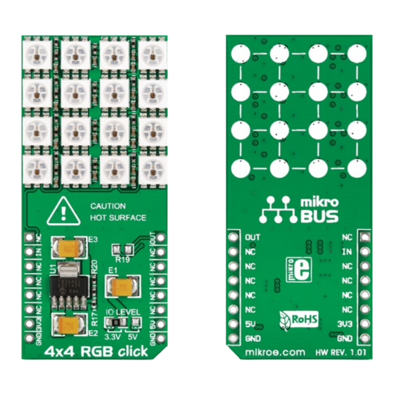
4x4 RGB
click
™
1. Introduction
4x4 RGB click
™
carries a matrix of 16
WS2812 RGB LEDs and a MCP1826 low
dropout regulator. These LEDs actually
consist of three single colored LEDs (Red,
Green and Blue), plus a control chip in a
single package. The LED matrix is connected
to the target board microcontroller through
the mikroBUS
™
RST pin. The board uses
either a 3.3V or 5V power supply.
2. Soldering the headers
Before using your click
™
board, make sure
to solder 1x8 male headers to both left and
right side of the board. Two 1x8 male headers
are included with the board in the package.
2
Turn the board upside down so that
the bottom side is facing you upwards.
Place shorter pins of the header into the
appropriate soldering pads.
1
3
Turn the board upward again. Make sure
to align the headers so that they are
perpendicular to the board, then solder the
pins carefully.
3. Plugging the board in
Once you have soldered the headers your
board is ready to be placed into the desired
mikroBUS
socket. Make sure to align the
™
cut in the lower-right part of the board with
the markings on the silkscreen at the
mikroBUS
socket. If all the
™
pins are aligned correctly,
push the board all the way
into the socket.
4. Essential features
The LED matrix can heat up so be careful
when using 4x4 RGB click
. Avoid touching
™
the board when it's in use, and don't drive
the LEDs to max brightness levels. With that
in mind, you can use the board to generate
colorful moving displays (RGB LED matrices
are commonly used for displaying graphics
on electronic billboards, signs, and similar).
click
™
BOARD
www.mikroe.com
4x4 RGB click
™
manual
ver 1.01
0 1 0 0 0 0 0 0 7 7 2 1 4
Advertisement

Subscribe to Our Youtube Channel
Related Manuals for mikroElektronika 4x4 RGB click


Summary of Contents for mikroElektronika 4x4 RGB click
- Page 1 ™ 4. Essential features The LED matrix can heat up so be careful when using 4x4 RGB click . Avoid touching ™ the board when it’s in use, and don’t drive the LEDs to max brightness levels. With that Turn the board upside down so that Turn the board upward again.
- Page 2 9. Support VCC-3.5V VCC-3.5V VCC-3.5V VCC-3.5V 100nF 100nF 100nF 100nF MikroElektronika offers free tech support L ED1 L ED2 L ED3 L ED4 (www.mikroe.com/support) until the end of RGB L ED RGB L ED RGB L ED RGB L ED the product’s lifetime, so if something goes...
Need help?
Do you have a question about the 4x4 RGB click and is the answer not in the manual?
Questions and answers