Table of Contents
Advertisement
WARNING: If the information in this manual is not
followed exactly, a fire or explosion may result causing
property damage, personal injury or loss of life.
— Do not store or use gasoline or other flammable va-
pors and liquids in the vicinity of this or any other
appliance.
— WHAT TO DO IF YOU SMELL GAS
• Do not try to light any appliance.
• Do not touch any electrical switch; do not use any
phone in your building.
• Immediately call your gas supplier from a neighbor's
phone. Follow the gas supplier's instructions.
• If you cannot reach your gas supplier, call the fire
department.
— Installation and service must be performed by a quali-
fied installer, service agency or the gas supplier.
INSTALLER: Leave this manual with the appliance.
CONSUMER: Retain this manual for future reference.
Questions, problems, missing parts? Before returning to your retailer, call
our customer service department at 1-866-573-0674, 8:00 am - 4:30 pm CST,
Monday through Friday or email customerservice@usaprocom.com
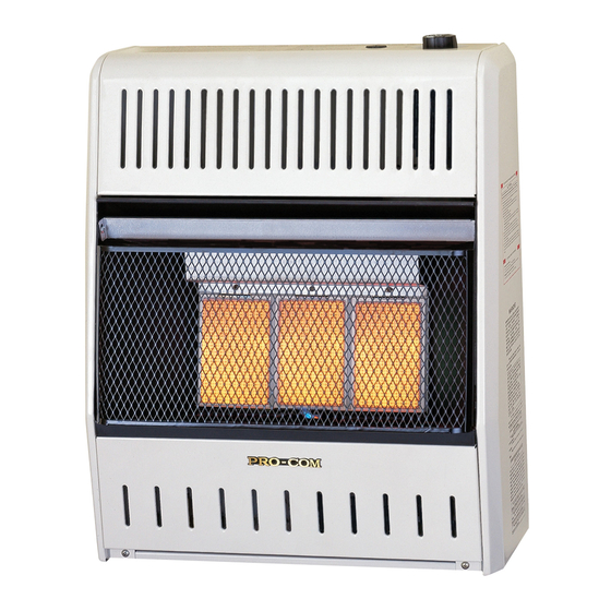
VENT-FREE NATURAL GAS
SPACE HEATER
OWNER'S OPERATION AND
INSTALLATION MANUAL
INFRARED MODELS
MN060HPA, MN100HPA
MN100TPA
Advertisement
Table of Contents

Related Manuals for Procom MN060HPA


Summary of Contents for Procom MN060HPA
- Page 1 VENT-FREE NATURAL GAS SPACE HEATER OWNER’S OPERATION AND INSTALLATION MANUAL INFRARED MODELS MN060HPA, MN100HPA MN100TPA WARNING: If the information in this manual is not followed exactly, a fire or explosion may result causing property damage, personal injury or loss of life.
-
Page 2: Table Of Contents
TABLE OF CONTENTS Safety ............3 Operation ..........16 Specifications ..........4 Inspecting Heater ........19 Preparing For Installation ......5 Care And Maintenance ......20 Qualified Installing Agency ......5 Troubleshooting ........21 Product Features ........5 Parts ............24 Local Codes.......... -
Page 3: Safety
SAFETY NATURAL GAS: Natural gas is odorless. An IMPORTANT: Read this owner’s odor-making agent is added to the gas. The manual carefully and completely odor helps you detect a gas leak. However, before trying to assemble, op- the odor added to the gas can fade. Gas may erate, or service this heater. -
Page 4: Specifications
SAFETY 1. Model MN060HPA shall not be installed 6. Always run heater with control knob at ON, in a bedroom. Models MN100HPA and LOW or HIGH locked positions. Never set MN100TPA shall not be installed in a control knob between locked positions. -
Page 5: Preparing For Installation
PREPARING FOR INSTALLATION Before beginning assembly or operation of the Ignitor Button product, make sure all parts are present. Com- Control Knob pare parts with package contents list. If any part is missing or damaged, do not attempt to assemble, install or operate the product. Con- tact customer service for replacement parts. -
Page 6: Local Codes
LOCAL CODES Install and use heater with care. Follow all State of Massachusetts: The installation local codes. In the absence of local codes, must be made by a licensed plumber or use the latest edition of The National Fuel gas fitter in the Commonwealth of Mas- Gas Code, ANSI Z223.1/NFPA 54*. -
Page 7: Air For Combustion And Ventilation
AIR FOR COMBUSTION AND VENTILATION heat loss in homes. Home owners weather WARNING: This heater shall strip and caulk around windows and doors not be installed in a confined space to keep the cold air out and the warm air in. During heating months, home owners want or unusually tight construction their homes as airtight as possible. - Page 8 AIR FOR COMBUSTION AND VENTILATION DETERMINING FRESH-AIR FLOW FOR HEATER LOCATION Determining if You Have a Confined or Unconfined Space Use this work sheet to determine if you have Example: a confined or unconfined space. Gas water heater __________ Btu/Hr 30,000 Vent-free heater + _________ Btu/Hr...
-
Page 9: Ventilation Air
AIR FOR COMBUSTION AND VENTILATION WARNING: If the area in which the heater may be operated is smaller than that defined as an unconfined space or if the building is of unusually tight construction, provide adequate combustion and ventilation air by one of the methods described in the National Fuel Gas Code, ANSI Z223.1/NFPA 54, the International Fuel Gas Code, or applicable local codes. -
Page 10: Installation
WARNING: Never install the See Air for Combustion and Ventilation, pages heater 7 through 9. • Model MN060HPA in a bed- CHECK GAS TYPE room Be sure your gas supply is right for your heat- • Models MN100HPA or er. -
Page 11: Locating Heater
INSTALLATION Removing Front Panel of Heater CEILING 1. Remove two screws near bottom corners of lower front panel. 36" 2. Pull bottom of lower front panel forward, Minimum 6" then down (see Figure 6). Minimum From Sides of Heater Right Side Left Side... - Page 12 INSTALLATION Marking Screw Locations 1. Drill holes at marked locations using 1. Tape mounting bracket to wall where 5/16" drill bit. For solid walls (concrete or heater will be located. Make sure mount- masonry), drill at least 1" deep. ing bracket is level. 2.
- Page 13 INSTALLATION Installing Bottom Mounting Bracket 9. Tighten both screws until heater is firmly 1. Install bottom bracket to heater bottom secured to wall. Do not over tighten. with two screws. It may be more conve- Note: Do not replace front panel at this time. nient to remove heater from wall bracket Replace front panel after making gas connec- to attach.
- Page 14 INSTALLATION Typical Inlet Pipe Diameters CAUTION: Use pipe joint Models up to 20,000 BTU/hr use 3/8" black sealant that is resistant to gas. iron pipe or greater. Models 25,000 BTU/hr and higher use 1/2" black iron pipe or greater. Before installing heater, make sure you have Installation must include an equipment shutoff the items listed below: valve, union, and plugged 1/8"...
-
Page 15: Checking Gas Connections
INSTALLATION CHECKING GAS CONNECTIONS Test Pressures Equal To or Less Than WARNING: Test all gas piping 1/2 PSIG (3.5 kPa) and connections for leaks after 1. Close equipment shutoff valve (see Fig- ure 13). installing or servicing. Correct 2. Pressurize supply piping system by either all leaks at once. -
Page 16: Operation
Then smell for gas, including near the lighting pilot again. floor. If you smell gas, STOP! Follow "B" in the safety information above. If you do Model MN060HPA not smell gas, go to the next step. 5. Push in gas control knob slightly and turn HIGH... - Page 17 OPERATION 8. To select the desired heating level, partially MN060HPA Control Knob press down the control knob slightly and turn counterclockwise . Release downward pressure on the knob while continuing to turn until the knob locks PILOT/IGN at the desired setting. The main burner should light.
-
Page 18: To Turn Off Gas To Appliance
OPERATION Note: If pilot does not stay lit, refer to Ignitor Electrode Thermocouple Troubleshooting, pages 21 though 23. Pilot Burner Also contact a qualified service technician or gas supplier for repairs. Until repairs are made, light pilot with match. To light pilot with match, see Manual Lighting Procedure. -
Page 19: Inspecting Heater
INSPECTING HEATER IMPORTANT: Owner’s should check pilot flame pattern and burner flame pattern often. Incorrect flame patterns indicate the need for cleaning (see Care and Maintenance, page 20) or service. WARNING: Only a qualified service person should service and repair heater. This includes maintenance requiring replacement or alteration of components. -
Page 20: Care And Maintenance
CARE AND MAINTENANCE WARNING: Turn off heater and let cool before servicing. CAUTION: You must keep control areas, burner, and circulating air passageways of heater clean. Inspect these areas of heater before each use. Have heater inspected yearly by a qualified service techni- cian. -
Page 21: Troubleshooting
TROUBLESHOOTING WARNING: If you smell gas: • Shut off gas supply. • Do not try to light any appliance. • Do not touch any electrical switch; do not use any phone in your building. • Immediately call your gas supplier from a neighbor’s phone. Fol- low the gas supplier’s instructions. - Page 22 TROUBLESHOOTING Problem Possible Cause Corrective Action ODS/pilot lights but flame 1. Control knob is not fully 1. Press in control knob fully. goes out when control pressed in. knob is released. 2. Control knob is not pressed 2. After ODS/pilot lights, keep in long enough.
- Page 23 TROUBLESHOOTING Problem Possible Cause Corrective Action Slight smoke or odor 1. Residues from manufactur- 1. Problem will stop after a few during initial operation. ing process. hours of operation. Heater produces a click- 1. Metal is expanding while 1. This is common with most ing/ticking noise just after heating or contracting while heaters.
-
Page 24: Parts
PARTS MODEL MN060HPA www.usaprocom.com 200048-01A... - Page 25 PARTS MODEL MN060HPA This list contains replaceable parts for your heater. When ordering replacement parts, follow the instructions listed under Replacement Parts on page 30 of this manual. ITEM PART # DESCRIPTION MB10008 Cabinet Assembly MB09003 Lower Front Panel ML006-02...
- Page 26 PARTS MODEL MN100HPA www.usaprocom.com 200048-01A...
- Page 27 PARTS MODEL MN100HPA This list contains replaceable parts for your heater. When ordering replacement parts, follow the instructions listed under Replacement Parts on page 30 of this manual. ITEM PART # DESCRIPTION MB10008 Cabinet Assembly MB09003 Lower Front Panel ML006-01 Reflector Unit MB19005 Burner Assembly...
- Page 28 PARTS MODEL MN100TPA www.usaprocom.com 200048-01A...
- Page 29 PARTS MODEL MN100TPA This list contains replaceable parts for your heater. When ordering replacement parts, follow the instructions listed under Replacement Parts on page 30 of this manual. ITEM PART # DESCRIPTION MB10007 Cabinet Assembly MB09003 Lower Front Panel ML006-01 Reflector Unit MB19005 Burner Assembly...
-
Page 30: Replacement Parts
• Purchase date ACCESSORIES Purchase these heater accessories from your local dealer. If they can not supply these acces- sories, contact ProCom Heating, Inc. at 1-866-573-6074 for information. EQUIPMENT SHUTOFF VALVE For all models. Equipment shutoff valve with 1/8" NPT tap. -
Page 31: Service Hints
TECHNICAL SERVICE You may have further questions about installation, operation, or troubleshooting. If so, contact ProCom Heating, Inc. at 1-866-573-6074. When calling, please have your model and serial numbers of your heater ready. www.usaprocom.com... -
Page 32: Warranty
We make no other warranty, expressed or implied. LIMITED WARRANTY ProCom Heating, Inc. warrants this product to be free from defects in materials and components for ONE (1) year from the date of first purchase, provided that the product has been properly installed by a qualified installer in accordance with all local codes and instructions furnished with the unit, operated and main- tained in accordance with all applicable instructions.
Need help?
Do you have a question about the MN060HPA and is the answer not in the manual?
Questions and answers