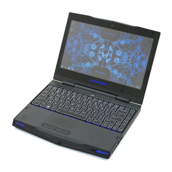
Alienware M11x MOBILE User Manual
Alienware m11x mobile manual
Hide thumbs
Also See for M11x MOBILE:
- Mobile manual (112 pages) ,
- Product manual (100 pages) ,
- Specifications (15 pages)
Table of Contents
Advertisement
Quick Links
Advertisement
Table of Contents

Subscribe to Our Youtube Channel
Related Manuals for Alienware M11x MOBILE


Summary of Contents for Alienware M11x MOBILE
- Page 1 ALIENWARE M11x MOBILE MANUAL ®...
- Page 2 Trademarks used in this manual: Alienware, AlienFX, and the AlienHead logo are trademarks or registered trademarks of Alienware Corporation; Dell is a trademark of Dell Inc.; Microsoft and Windows are either trademarks or registered trademarks of Microsoft Corporation in the United States and/or other countries; Intel, Pentium, and SpeedStep are registered trademarks and Core is a trademark of Intel Corporation in the U.S.
-
Page 3: Table Of Contents
CONTENTS CHAPTER 1:SETTING UP YOUR LAPTOP ..........9 Before Setting Up Your Laptop . - Page 4 Alienware Command Center . . . . . . . . . . . . . . . . . . .
- Page 5 CONTACTING ALIENWARE . . . . . . . . . . . . . . . . . . .
- Page 7 We invite you to share your experience with your new high‑performance mobile with us, so please do not hesitate to either e-mail or call Alienware with any questions or concerns. The entire staff shares your enthusiasm for new technology and we hope that you enjoy using your new mobile as much as Alienware enjoyed building it for you.
-
Page 9: Chapter 1:Setting Up Your Laptop
CHAPTER 1: SETTING UP YOUR LAPTOP CHAPTER 1: SETTING UP YOUR LAPTOP... -
Page 10: Before Setting Up Your Laptop
CHAPTER 1: SETTING UP YOUR LAPTOP Before Setting Up Your Laptop Congratulations on the purchase of your Alienware M11x! ® Read all safety and setup instructions before connecting your new laptop. Begin by carefully opening the box and removing all components that were shipped to you. - Page 11 CHAPTER 1: SETTING UP YOUR LAPTOP Product Documentation and Media The documentation that ships with your Alienware laptop is designed to provide answers ® to many of the questions that may arise as you explore your new laptop’ s capabilities. You may see the documentation for technical information or general use as needed to answer questions in the future, or aid you in finding answers and solutions.
-
Page 12: Connect The Ac Adapter
CHAPTER 1: SETTING UP YOUR LAPTOP Connect the AC Adapter WARNING: The AC adapter works with electrical outlets worldwide. However, power connectors and power strips vary among countries. Using an incompatible cable or improperly connecting the cable to a power strip or electrical outlet may cause fire or equipment damage. -
Page 13: Press The Power Button
CHAPTER 1: SETTING UP YOUR LAPTOP Press the Power Button... -
Page 14: Connect The Network Cable (Optional)
CHAPTER 1: SETTING UP YOUR LAPTOP Connect the Network Cable (Optional) -
Page 15: Set Up Microsoft Windows
CHAPTER 1: SETTING UP YOUR LAPTOP Set Up Microsoft Windows Your computer is preconfigured with the Microsoft ® Windows ® operating system. To set up Windows for the first time, follow the instructions on the screen. These steps are mandatory and may take some time to complete. -
Page 16: Create System Recovery Media (Recommended)
CHAPTER 1: SETTING UP YOUR LAPTOP Create System Recovery Media (Recommended) NOTE: It is recommended that you create a system recovery media as soon as you set up Microsoft Windows. The system recovery media can be used to restore your computer to the operating state it was in when you purchased the computer, while preserving data files (without the need of the Operating System disc). - Page 17 CHAPTER 1: SETTING UP YOUR LAPTOP To create a system recovery media: Ensure that the AC adapter is connected (see “Connect the AC Adapter” on page 12). Insert the disc or USB key in the computer. → Programs→ AlienRespawn. Start Click Recovery Media.
-
Page 18: Connect To The Internet (Optional)
CHAPTER 1: SETTING UP YOUR LAPTOP Connect to the Internet (Optional) Setting Up a Wired Connection • If you are using a dial‑up connection, connect the telephone line to the optional external USB modem and to the telephone wall jack before you set up your Internet connection. •... -
Page 19: Setting Up A Wireless Connection
CHAPTER 1: SETTING UP YOUR LAPTOP Setting Up a Wireless Connection NOTE: To set up your wireless router, see the documentation that shipped with your router. Before you can use your wireless Internet connection, you need to connect to your wireless router. -
Page 20: Setting Up Your Internet Connection
CHAPTER 1: SETTING UP YOUR LAPTOP Setting Up Your Internet Connection ISPs and ISP offerings vary by country. Contact your ISP for offerings available in your country. If you cannot connect to the Internet but have successfully connected in the past, the Internet Service Provider (ISP) might have a service outage. -
Page 21: Chapter 2: Getting To Know Your Laptop
CHAPTER 2: GETTING TO KNOW YOUR LAPTOP CHAPTER 2: GETTING TO KNOW YOUR LAPTOP... -
Page 22: Left View Features
CHAPTER 2: GETTING TO KNOW YOUR LAPTOP This chapter provides information about your new laptop to familiarize you with its various features, and get you up and running quickly. Left View Features... - Page 23 CHAPTER 2: GETTING TO KNOW YOUR LAPTOP Security cable slot — Attaches a commercially available security cable to the computer. NOTE: Before you buy a security cable, ensure that it fits into the security cable slot on your computer. DisplayPort connector —...
- Page 24 CHAPTER 2: GETTING TO KNOW YOUR LAPTOP USB connector with USB PowerShare — Connects to USB devices, such as a mouse, keyboard, printer, external drive, or MP3 player. The USB Powershare feature allows you to charge USB devices when the computer is powered on/off or in sleep state.
- Page 25 CHAPTER 2: GETTING TO KNOW YOUR LAPTOP 3-in-1 Media Card Reader — Provides a fast and convenient way to view and share digital photos, music, videos, and documents. IEEE 1394 A connector — Connects to high‑speed serial multimedia devices such as digital video cameras. 8 SIM card slot —...
-
Page 26: Right View Features
CHAPTER 2: GETTING TO KNOW YOUR LAPTOP Right View Features Audio out/Headphone connectors (2) — Connect to a pair of headphones or to a powered speaker or sound system. Audio in/Microphone connector — Connects to a microphone or inputs signal for use with audio programs. -
Page 27: Back View Features
CHAPTER 2: GETTING TO KNOW YOUR LAPTOP Back View Features AC adapter connector — Connects to an AC adapter to power the computer and charge the battery. -
Page 28: Display Features
CHAPTER 2: GETTING TO KNOW YOUR LAPTOP Display Features 1 2 3... - Page 29 CHAPTER 2: GETTING TO KNOW YOUR LAPTOP Microphone — Provides high quality sound for video conferencing and voice recording. 2 Camera — Built‑in camera for video capture, conferencing, and chat. 3 Camera activity indicator — Indicates if the camera is on or off. 4 Display —...
-
Page 30: Computer Base And Keyboard Features
CHAPTER 2: GETTING TO KNOW YOUR LAPTOP Computer Base and Keyboard Features... - Page 31 CHAPTER 2: GETTING TO KNOW YOUR LAPTOP Power button — Turns the computer on or off when pressed. For more information, see “Power Button” on page 32. 2 Keyboard — The backlit keyboard provides visibility in dark environments by illuminating all symbols on the keys. 3 Touch pad buttons (2) —...
-
Page 32: Power Button
CHAPTER 2: GETTING TO KNOW YOUR LAPTOP Power Button You can program this button to perform actions like shutting down the operating system or entering the standby mode. For details on how to program this button, see Power Options in the control panel of Microsoft Windows operating system. - Page 33 CHAPTER 2: GETTING TO KNOW YOUR LAPTOP On AC adapter: Blue or custom AC‑color The battery is fully charged. Blue or custom AC‑color fading into The computer is turned off or on and white or custom battery‑color the battery is charging. Blue or custom AC‑color fading into The computer is in standby mode.
-
Page 34: Function Keys
CHAPTER 2: GETTING TO KNOW YOUR LAPTOP Function Keys NOTE: Depending on the configuration of the laptop you purchased, some of the function keys may have no associated tasks. The <Fn> key is located near the bottom-left corner of the keyboard, and is used together with other keys to activate certain functions. - Page 35 CHAPTER 2: GETTING TO KNOW YOUR LAPTOP F5 — Decrease Display Brightness Press <Fn><F5> to decrease the brightness of the display. F7 — Mute on/off Press <Fn><F7> to enable or disable the mute function. F8 — Decrease volume Press <Fn><F8> to decrease the volume level. F9 —...
- Page 36 CHAPTER 2: GETTING TO KNOW YOUR LAPTOP PAUSE — Alienware Command Center Press <Fn><PAUSE> to access Alienware Command Center (for more information, see “Alienware Command Center” on page 38). PRT SCRN — AlienFX Press <Fn><PRT SCRN> to enable or disable the AlienFX illumination.
-
Page 37: Chapter 3: Using Your Laptop
CHAPTER 3: USING YOUR LAPTOP CHAPTER 3: USING YOUR LAPTOP... -
Page 38: Alienware Command Center
The Alienware ® Command Center gives you access to Alienware’ s exclusive software and is a continuously upgradable control panel. As Alienware releases new programs, they download directly into the Command Center allowing you to build a library of system management, optimization, and customization tools. - Page 39 CHAPTER 3: USING YOUR LAPTOP Connection Type Computer Cable Display HDMI‑to‑HDMI (HDMI cable) DisplayPort- to-DisplayPort (DisplayPort cable) DisplayPort-to-DVI (DisplayPort-to- DVI adapter + DVI cable) NOTE: You can purchase the DisplayPort-to-DVI adapter and additional HDMI cables at www.dell.com.
- Page 40 Turn off the display and disconnect it from the power supply. Connect one end of the display cable to the DisplayPort, or HDMI connector on your Alienware laptop. Connect the other end of the cable to the same connector on your display.
-
Page 41: Extending The Desktop
CHAPTER 3: USING YOUR LAPTOP Extending the Desktop With the external display connected, right‑click on the desktop and select Personalize. Select Connect to a projector or other external display in the upper left portion of the screen. Click Connect Display. Select from the below options that appear on the screen: •... -
Page 42: Using The Wireless Control
CHAPTER 3: USING YOUR LAPTOP Using the Wireless Control The wireless control allows you to quickly turn all of your wireless radios (Bluetooth ® , WLAN, and WWAN) off, such as when you are asked to disable all wireless radios on an airplane flight. Press <Fn><F3>to turn on all radios. - Page 43 CHAPTER 3: USING YOUR LAPTOP Battery Meter...
-
Page 44: Power Management
CHAPTER 3: USING YOUR LAPTOP Power Management Understanding Power Consumption In order to fully utilize the power of your battery, it would be a good idea for you to spend some time acquiring a basic understanding of the power management concept from your operating system. -
Page 45: Reducing Power Consumption
Although your laptop (together with the operating system) is capable of power conservation, there are measures you can take to reduce the power consumption: • Lower the intensity of the display backlight. A very bright screen translates to higher power usage. • Go Dark mode in the Alienware command centre. Use the... -
Page 46: Nvidia Optimus Technology
CHAPTER 3: USING YOUR LAPTOP nVidia Optimus Technology Your Alienware M11x laptop is equipped with nVidia’ s Optimus technology. The Optimus technology is designed to maximize performance and user experience on your computer, while minimizing the impact on battery life. It enables you to combine the graphic processing... - Page 47 CHAPTER 3: USING YOUR LAPTOP Changing the Application Profile Settings Right‑click on the desktop and select NVIDIA Control Panel. NVIDIA Control Panel window, click 3D Settings to expand the selection (if not In the already expanded) and then click Manage 3D Settings. In the Program Settings tab, click Add and browse to select the application’...
-
Page 48: Configuring The Bios
CHAPTER 3: USING YOUR LAPTOP Configuring the BIOS System Setup The System Setup options allow you to: • Change the system configuration information after you add, change, or remove any hardware in your laptop. • Set or change a user‑selectable option. •... -
Page 49: Entering System Setup
CHAPTER 3: USING YOUR LAPTOP Entering System Setup Turn on (or restart) your laptop. NOTE: Keyboard failure may result when a key on the keyboard is held down for extended periods of time. To avoid possible keyboard failure, press and release <F2> in even intervals until the System Setup screen appears. -
Page 50: System Setup Options
Main Menu System Time Displays the system time. System Date Displays the system date. Alienware Displays the model number of your computer. Service Tag Displays the service tag of your computer. BIOS Version Displays the BIOS version. EC Version Displays the EC firmware version. - Page 51 CHAPTER 3: USING YOUR LAPTOP Main Menu CPU ID Displays the ID of the processor. Total Memory Displays the total memory available in your computer. Memory Bank 0 Displays the memory size installed in DIMM 0. Memory Bank 1 Displays the memory size installed in DIMM 1. Advanced Menu Intel SpeedStep ®...
- Page 52 CHAPTER 3: USING YOUR LAPTOP Advanced Menu USB Wake Support Allows you to enable USB devices to wake the computer from standby or to disable the USB wake support feature. NOTE: If USB Powershare is enabled, a device connected to the USB Powershare connector may not wake the computer.
- Page 53 CHAPTER 3: USING YOUR LAPTOP Advanced Menu SD Card Reader Allows you to enable or disable the internal SD card reader. CPU Turbo Mode Allows you to enable or disable the Intel CPU turbo mode performance option. CPU Over-Clocking Allows you to enable or disable CPU bus clock Over-Clocking •...
- Page 54 CHAPTER 3: USING YOUR LAPTOP Advanced Menu Adapter Warnings Allows you to choose if the computer should display warning messages when you use certain power adapters. The computer displays these messages if you attempt to use a power adapter that has too little capacity for your configuration. •...
- Page 55 CHAPTER 3: USING YOUR LAPTOP Wireless Menu Bluetooth Allows you to enable or disable the internal Bluetooth device. • Disabled: The internal Bluetooth device is disabled and is not visible to the operating system. • Enabled: The internal Bluetooth device is enabled. Wireless Network Allows you to enable or disable the internal wireless device.
-
Page 56: Set User Password
CHAPTER 3: USING YOUR LAPTOP Security Menu Set User Password Allows you to set the user password. The user password controls access to the computer at boot. Boot Menu Use the <F5> or <F6> keys to change the boot device priority. You can choose from: •... - Page 57 CHAPTER 3: USING YOUR LAPTOP Exit Menu Exit Saving Allows you to exit System Setup and save your changes to Changes CMOS. Save Change Allows you remain in System Setup and save your changes to Without Exit CMOS. Exit Discarding Allows you to exit System Setup and load previous values from Changes CMOS for all Setup items.
- Page 58 CHAPTER 3: USING YOUR LAPTOP...
-
Page 59: Chapter 4: Installing And Replacing Components
CHAPTER 4: INSTALLING AND REPLACING COMPONENTS CHAPTER 4: INSTALLING AND REPLACING COMPONENTS... -
Page 60: Before You Begin
You can purchase components for your computer at www.dell.com or www.alienware.com. NOTE: See the Service Manual at support.dell.com/manuals for installation instructions of all serviceable components. Parts purchased from Dell and Alienware will ship with specific replacement instructions. Before You Begin This section provides procedures for removing and installing the components in your laptop. -
Page 61: Turning Off Your Computer
CHAPTER 4: INSTALLING AND REPLACING COMPONENTS Turning Off Your Computer CAUTION: To avoid losing data, save and close all open files and exit all open programs before you turn off your laptop. Save and close all open files and exit all open programs. →... -
Page 62: Before Working Inside Your Computer
CHAPTER 4: INSTALLING AND REPLACING COMPONENTS Before Working Inside Your Computer Use the following safety guidelines to help protect your computer from potential damage and to help to ensure your own personal safety. WARNING: Before working inside your laptop, read the safety information that shipped with your computer. - Page 63 CHAPTER 4: INSTALLING AND REPLACING COMPONENTS CAUTION: To avoid damaging the computer, perform the following steps before you begin working inside the computer. Ensure that the work surface is flat and clean to prevent the computer cover from being scratched. Turn off your computer (for more information, see “Turning Off Your Computer”...
-
Page 64: Replacing The Battery Pack
This battery pack can easily be removed and replaced. Ensure that the laptop is properly shut down before changing the battery pack. CAUTION: To avoid damage to the laptop, use only the battery designed for this particular Alienware laptop. Do not use batteries designed for other Alienware or Dell laptops. To remove the battery pack: Follow the instructions in “Before You Begin”... - Page 65 CHAPTER 4: INSTALLING AND REPLACING COMPONENTS captive screws (8) 2 base cover...
- Page 66 CHAPTER 4: INSTALLING AND REPLACING COMPONENTS Remove the two screws that secure the battery pack to the computer base. Disconnect the battery pack cable from the connector on the system board. Lift and slide the battery pack out of the computer. battery pack 3 battery pack cable 2 screws (2)
-
Page 67: Upgrading Or Replacing Memory
CHAPTER 4: INSTALLING AND REPLACING COMPONENTS Upgrading or Replacing Memory Your laptop is equipped with a configurable memory unit. The industry standard JEDEC PC3-8500/PC3-10600 (DDR3) SODIMM memory module connectors are available for memory upgrade. The table below illustrates all the possible ways system memory can be configured. Memory connector #1 Memory connector #2 Total memory... -
Page 68: Removing The Memory Module(S)
CHAPTER 4: INSTALLING AND REPLACING COMPONENTS Removing the Memory Module(s) Follow the instructions in “Before You Begin” on page Remove the battery (see “Replacing the Battery Pack” on page 64). Use your fingertips to carefully spread apart the memory module connector’ s spring-locks until the module pops up. - Page 69 CHAPTER 4: INSTALLING AND REPLACING COMPONENTS To replace the memory modules, perform the removal steps in reverse order. While inserting the memory module into the connector align the notch on the memory module with the tab on the memory module connector. NOTE: If you need to install memory modules in two connectors, install a memory module in the lower connector before you install a memory module in the upper connector.
-
Page 70: Upgrading Or Replacing The Hard Drive Assembly
CHAPTER 4: INSTALLING AND REPLACING COMPONENTS Upgrading or Replacing the Hard Drive Assembly Your laptop is equipped with one hard drive socket. Removing the Hard Drive Follow the instructions in “Before You Begin” on page Remove the battery (see “Replacing the Battery Pack” on page 64). - Page 71 CHAPTER 4: INSTALLING AND REPLACING COMPONENTS hard drive 2 pull-tab Remove the four screws that secure the hard drive to the hard drive bracket. Lift the hard drive bracket of the hard drive according to the illustration.
- Page 72 CHAPTER 4: INSTALLING AND REPLACING COMPONENTS hard drive bracket 3 hard drive 2 screws (4)
- Page 73 CHAPTER 4: INSTALLING AND REPLACING COMPONENTS Remove the interposer from the hard drive. hard drive 2 interposer To replace the hard drive, perform the removal steps in reverse order.
- Page 74 CHAPTER 4: INSTALLING AND REPLACING COMPONENTS...
-
Page 75: Chapter 5: Troubleshooting
CHAPTER 5: TROUBLESHOOTING CHAPTER 5: TROUBLESHOOTING... -
Page 76: Basic Hints And Tips
CHAPTER 5: TROUBLESHOOTING Basic Hints and Tips • Computer does not power on: Is your AC adapter cable securely connected to a working electrical outlet? If connected to a power strip, ensure that the strip is actually working. • Connections: Check all the cables to ensure that there are no loose connections anywhere. -
Page 77: Backup And General Maintenance
CHAPTER 5: TROUBLESHOOTING Backup and General Maintenance • Always backup your important data on a regular basis and keep copies of your operating system and software safe. Do not forget to note the serial numbers if you are storing them outside of their original cases ‑ e.g., in a CD wallet. •... - Page 78 • If an error message appears on the screen, write down the exact error message prior to calling Alienware Technical Support to aid in diagnosing and resolving your issue. • If an error occurs in a specific program, see the program’ s documentation.
-
Page 79: Software Diagnostic Tools
To invoke PSA: Turn on (or restart) your computer. Shut down and restart the laptop. When the Alienware logo appears, press <F12> immediately. NOTE: If you wait too long and the operating system logo appears, continue to wait... - Page 80 CHAPTER 5: TROUBLESHOOTING If the Pre-boot System Assessment completes successfully, the following message appears “Do you want to run the remaining memory tests? This will take about 30 minutes or more. Do you want to continue? (Recommended).” If you are experiencing memory issues, press <y>, otherwise press <n>. The following message is displayed: “Pre-boot System Assessment complete.”...
- Page 81 NOTE: Back up all data before initiating a system recovery. Review your laptop’ s configuration information, and ensure that the device that you want to test displays in the system setup program and is active. Start the Alienware Diagnostics from the backup disc.
- Page 82 NOTE: Write down any error codes and problem descriptions exactly as they appear and follow the instructions on the screen. After all tests have completed, close the test window to return to the Alienware Diagnostics Main Menu. Main Menu window to exit the Alienware Remove the backup disc, then close the Diagnostics and restart the computer.
-
Page 83: Answers To Common Problems
However, if the computer fails the POST, the computer will generate a single beep to indicate a general failure and an error message will be displayed. For assistance, contact Alienware Technical Support (see “CONTACTING ALIENWARE“ on page 113). The computer stops responding or a solid blue screen appears CAUTION: You might lose data if you are unable to perform an operating system shutdown. -
Page 84: A Program Stops Responding Or Crashes Repeatedly
CHAPTER 5: TROUBLESHOOTING A program stops responding or crashes repeatedly End the program: Press <Ctrl><Shift><Esc> simultaneously. Applications tab and select the program that is no longer responding. Click the End Task. Click Check the software documentation. If necessary, uninstall and then reinstall the program. ®... -
Page 85: Other Software Problems
CHAPTER 5: TROUBLESHOOTING Other software problems Back up your files immediately Use a virus-scanning program to check the hard drive, or CDs Save and close any open files or programs and shut down your computer through the Start menu Scan the computer for spyware: If you are experiencing slow computer performance, you frequently receive pop‑up advertisements, or you are having problems connecting to the Internet, your computer might be infected with spyware. - Page 86 CHAPTER 5: TROUBLESHOOTING Check the software documentation or contact the software manufacturer for troubleshooting information: • Ensure that the program is compatible with the operating system installed on your computer. • Ensure that your computer meets the minimum hardware requirements needed to run the software.
-
Page 87: Hard Drive Problems
CHAPTER 5: TROUBLESHOOTING Hard Drive Problems Allow the computer to cool before turning it on A hot hard drive may prevent the operating system from starting. Try allowing the computer to return to room temperature before turning it on. Run Check Disk →... -
Page 88: If The Display Is Blank
(see “Upgrading or Replacing Memory” on page 67). • Computers using a dual-channel memory configuration require that memory modules be installed in pairs. If you require assistance, contact Alienware Technical Support (for more information, see “CONTACTING ALIENWARE“ on page 113). Display... - Page 89 Check that the wall outlet is working properly by testing another device such as a radio or lamp that you know works. If the wall outlet is not working, contact an electrician or your power company for further assistance. • If the problem persists, contact Alienware support (see “CONTACTING ALIENWARE“ on page 113).
- Page 90 CHAPTER 5: TROUBLESHOOTING...
-
Page 91: Chapter 6: System Recovery
CHAPTER 6: SYSTEM RECOVERY CHAPTER 6: SYSTEM RECOVERY... -
Page 92: Alienrespawn/Datasafe Local Backup
CHAPTER 6: SYSTEM RECOVERY AlienRespawn/DataSafe NOTE: AlienRespawn/DataSafe Local Backup may not be available in all Local Backup regions. You can use AlienRespawn/DataSafe Local CAUTION: Using AlienRespawn/ Backup to restore your hard drive to the DataSafe Local Backup permanently removes any programs or drivers operating state it was in when you purchased your computer, while preserving data files. - Page 93 353560 at support.dell.com. NOTE: Do not disconnect the AC adapter. Turn on your computer. When the Alienware logo appears, ™ press <F8> several times to access the Advanced Boot Options window. NOTE: If you wait too long and the...
-
Page 94: Dell Datasafe Online Backup
CHAPTER 6: SYSTEM RECOVERY more information, Dell DataSafe Online Backup delldatasafe.com. To schedule backups: NOTE: Dell DataSafe Online is supported Double‑click the Dell DataSafe Online only on Windows operating systems. icon on the taskbar. NOTE: A broadband connection is Follow the instructions that appear on recommended for fast upload/download the screen. -
Page 95: Chapter 7: Specifications
CHAPTER 7: BASIC SPECIFICATIONS CHAPTER 7: SPECIFICATIONS... - Page 96 CHAPTER 7: SPECIFICATIONS Computer Model Alienware M11x‑R2 Dimensions Height (front and back) 32.7 mm (1.29 inches) Width 285.7 mm (11.25 inches) Depth 233.3 mm (9.19 inches) Weight with 8‑cell battery 2.0 kg (4.4 lbs) (starting at) NOTE: The weight of your laptop will vary depending on the configuration ordered and the manufacturing variability.
- Page 97 CHAPTER 7: SPECIFICATIONS Processor and System Chipset Processor Intel Core™ i3 ® Intel Core i5 Intel Core i7 Intel Pentium U5400 ® L2 cache 256 KB L3 cache up to 4 MB Bus clock 133 Mhz System chipset Intel QS57 SDRAM bus width one or two 64-bit channels of DDR3 memory up to 1333 MHz...
- Page 98 CHAPTER 7: SPECIFICATIONS Memory Connectors two internally-accessible DDR3 SODIMM sockets Capacities 1 GB, 2 GB, and 4 GB Memory type 1066 MHz and 1333 MHz (operates at 800 Mhz) dual-channel DDR3 configurations NOTE: Chipset allows memory to run only at 800 Mhz. Memory configurations 2 GB, 3 GB, 4 GB, and 8 GB possible...
- Page 99 CHAPTER 7: SPECIFICATIONS Ports and Connectors Network adapter one RJ45 connector three 4-pin USB 2.0-compliant connectors, including one USB PowerShare connector HDMI one 19‑pin connector DisplayPort one 20‑pin connector Audio two audio output/headphone connectors and one audio input/microphone connector 3-in-1 Media Card Reader one combo connector SIM card one SIM card slot...
- Page 100 CHAPTER 7: SPECIFICATIONS Video Video controller Integrated Intel HD Graphics Discrete NVIDIA GeForce GT335M Video memory dynamic based on system memory capacity Integrated Discrete 1 GB External display support HDMI and DisplayPort Audio Controller Intel High Definition Audio Speaker single 8‑ohms speakers in both the left and right speaker assembly Internal speaker amplifier up to 1 W per channel;...
- Page 101 CHAPTER 7: SPECIFICATIONS Hard-Drive Storage Interface SATA Number of hard drives Hard drive 2.5 inch SATA hard drive Type standard portable and solid‑state hard‑drives Cards Supported • Media cards Secure Digital (SD) memory card • MultiMedia Card (MMC) • Memory Stick PRO •...
- Page 102 CHAPTER 7: SPECIFICATIONS Display Type 11.6 inch HD TrueLife, WLED Maximum resolution 1366 x 768 Dimensions Height 144 mm (5.67 inches) Width 256.12 mm (10.08 inches) Diagonal 293.83 mm (11.57 inches) Refresh rate 60 Hz Operating angle 0° (closed) to 140° Pixel pitch 0.2550 mm Controls...
- Page 103 82 (Korea, U.S., and Canada); 83 (Europe); 86 (Japan) Backlight color RGB; colors can be changed by invoking the AlienFX ® application in the Alienware Command Center. For information, see “Alienware Command Center” on page 38. Touch Pad X/Y position resolution...
- Page 104 CHAPTER 7: SPECIFICATIONS Battery 8-cell “smart” lithium ion (63 Whr) Height 11.2 mm (0.44 inches) Width 173 mm (6.81 inches) Depth 109.4 mm (4.31 inches) Weight 0.43 kg (0.94 lb) Voltage 14.8 V Operating time battery operating time varies depending on operating conditions and can be significantly reduced under certain power‑intensive conditions.
- Page 105 CHAPTER 7: SPECIFICATIONS AC Adapter Type 65 W/90 W Input voltage 100-240 VAC Input current (maximum) 65 W 1.7 A 90 W 1.5 A Input frequency 50-60 Hz Output current 65 W 3.34 A (continuous) 90 W 4.62 A (continuous) Output power 65 W 65 W...
- Page 106 CHAPTER 7: SPECIFICATIONS AC Adapter Temperature range Operating 0° to 40°C (32° to 104°F) Storage –40° to 70°C (–40° to 158°F) Connector types DC connector 3-pin, 7.4 mm plug AC connector 3-pin – C6 (65 W) 3-pin – C6 (90 W) Computer Environment Temperature range Operating...
- Page 107 CHAPTER 7: SPECIFICATIONS Computer Environment Maximum vibration (using a random vibration spectrum that simulates user environment) Operating 0.66 GRMS Storage 1.3 GRMS Maximum shock (Measured with hard drive in operating status and a 2‑ms half‑sine pulse for operating. Also measured with hard drive in head‑parked position and a 2‑ms half‑sine pluse for storage) Operating 110 G...
- Page 108 CHAPTER 7: SPECIFICATIONS...
-
Page 109: Appendix
APPENDIX APPENDIX... -
Page 110: General And Electrical Safety Precautions
APPENDIX GENERAL AND ELECTRICAL SAFETY PRECAUTIONS Computer Setup • Read all instructions marked on the product and in the documentation before operating your computer. • Retain all safety and operating instructions. • Never use this product near water or a heat source. •... - Page 111 APPENDIX Computer Use • Route the power cable and all cables away from where people might walk or trip over them. Do not allow anything to rest on the power cable. • Do not spill anything on or into your computer. •...
- Page 112 Your computer was dropped or the case was damaged. • Normal operation of the computer does not occur when the operating instructions are followed. Replacement Components or Accessories It is only advised to use replacement parts or accessories recommended by Alienware.
-
Page 113: Contacting Alienware
APPENDIX CONTACTING ALIENWARE For customers in the United States/Canada, call 1‑800‑ALIENWARE. NOTE: If you do not have an active Internet connection, you can find contact information on your purchase invoice, packing slip, bill, or Dell product catalog. Dell provides several online and telephone‑based support and service options. Because availability varies by country and product, some services may not be available in your area. - Page 114 APPENDIX Websites You can learn about Alienware products and services on the following websites: • www.dell.com • www.dell.com/ap (Asian/Pacific countries only) • www.dell.com/jp (Japan only) • www.euro.dell.com (Europe only) • www.dell.com/la (Latin American and Caribbean countries) • www.dell.ca (Canada only) You can access Alienware Support through the following websites: •...
- Page 115 APPENDIX Information for NOM, or Official Mexican Standard (Only for Mexico) The following information is provided in the device(s) described in this document in accordance with the requirements of the Official Mexican Standard (NOM): Importer: Dell México S.A. de C.V. Paseo de la Reforma 2620 - Flat 11°...
Need help?
Do you have a question about the M11x MOBILE and is the answer not in the manual?
Questions and answers