Table of Contents
Advertisement
Available languages
Available languages
Installation, Service and User Instructions
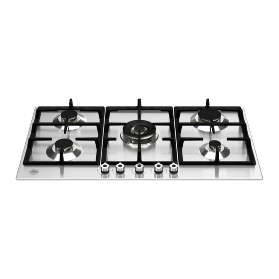
Built-in gas hotplates
DIMENSIONS: 35
IMPORTANT: SAVE FOR LOCAL ELECTRICAL INSPECTOR'S USE.
READ AND SAVE THESE INSTRUCTIONS FOR FUTURE REFERENCE.
OBSERVE ALL GOVERNING CODES AND ORDINANCES.
WARNING: If the information in this manual is not followed exactly, a fire or
explosion may result causing property damage, personal injury or death.
Do not store or use gasoline or other flammable vapors and liquid in the vicinity of
this or any other appliance.
WHAT TO DO IF YOU SMELL GAS
- Do not try to light any appliance.
- Do not touch any electrical switch.
- Do not use any phone in your building.
- Immediately call your gas supplier from a neighbor's phone. Follow
the gas supplier's instructions.
- If you cannot reach your gas suppliers, call the fire department.
Installation and service must be performed by a qualified installer, service agency
or the gas supplier.
Read this instruction booklet before installing and using the appliance.
The manufacturer will not be responsible for any damage to property or to persons caused by
incorrect installation or improper use of the appliance.
The manufacturer reserves the right to make changes to its products when considered necessary and useful,
without affecting the essential safety and operating characteristics.
This appliance has been designed for non-professional, domestic use only.
(French version page 10)
13/16
Models P310..L4X(2
BERTAZZONI
''
(W) x 21
(910 mm)
''
11/16
(550 mm)
5)D
OR
Advertisement
Table of Contents

Related Manuals for Bertazzoni P310..L4X(2 OR 5)D


Summary of Contents for Bertazzoni P310..L4X(2 OR 5)D
- Page 1 Installation, Service and User Instructions (French version page 10) BERTAZZONI Built-in gas hotplates DIMENSIONS: 35 ’’ (W) x 21 ’’ 13/16 (910 mm) 11/16 (550 mm) Models P310..L4X(2 IMPORTANT: SAVE FOR LOCAL ELECTRICAL INSPECTOR’S USE. READ AND SAVE THESE INSTRUCTIONS FOR FUTURE REFERENCE.
-
Page 2: Table Of Contents
INDEX: Installation Instructions……………………………………..………………………..pag.2 Inserting the hotplate……………………………………………..…………………..pag.3 Requirements……………………………………..……………………………….…..pag.3 Attaching the hotplate……………………………………..………………………….pag.3 Gas connection……………………………………..…………………………………pag.4 Electrical connection……………………………………..……………………….…..pag.4 Wiring diagrams……………………………………..…………………………….…..pag.5 Room ventilation…………………………………….…………………………………pag.5 Location and venting…………………………………….…………………………….pag.5 Replacement of nozzles……………………………………..………………………..pag.5 Regulation of burners……………………………………………...………………….pag.5 Descriptions…………………………………………………………………………….pag.6 Service & maintenance instructions……………………………..…………………..pag.6 Greasing the valves……………………………………………..…………………….pag.6 User instructions……………………………………………..………………………..pag.6 Using burners……………………………………………………..……………………pag.7 Cleaning the appliance……………………………………………..…………………pag.8 Figures………………………………………………...…………..……………………pag.19-20-21 Installation instructions This appliance shall only be installed by an authorized person. -
Page 3: Inserting The Hotplate
Inserting the hotplate After having removed the various loose parts from the internal and external packing, make sure that the hotplate in not damaged and is suitable for the specific gas usage. The gas type label is on the underside of the hotplate base. -
Page 4: Gas Connection
Gas connection Before connecting the appliance to the gas supply, first remove the plastic plug on which is press- fitted into the gas inlet union; to remove, just pull it off. 1. Check the ‘gas type’ sticker attached to the hotplate. Details of the injector sizes used are recorded on the data plate located on the base of the appliance. -
Page 5: Wiring Diagrams
Wiring diagram: see Fig. 10 Wiring diagram description 1. Cable terminal 2. Spark generator 3. Ignition spark L. Black N. White T. Green (earth) Room ventilation – Location and venting. ATTENTION: An exhaust fan may be used with the appliance; in each case it shall be installed in conformity with the national standards in force. -
Page 6: Descriptions
To convert the regulator for use with the other gas different from which one it is pre-arranged it is enough perform the following operations: 1) Unscrew by hand the upper metal stopper of the regulator (Fig. 5). 2) Unscrew by hand the white plastic piece screwed under the above mentioned metal stopper, afterward screw it again in opposite way under the metal stopper (for gas reference see the written “LP”... -
Page 7: Using Burners
Do not store dangerous or flammable material in the cabinet areas above appliance; store them in a safe place in order to avoid potential hazards. For safe use of appliance, do not use it for space heating. Do not use aerosol sprays in the vicinity of this appliance while it is in operation For description of hotplates refer to installation instructions. -
Page 8: Cleaning The Appliance
appliance may require additional ventilation, for example by opening a window, or increasing the power of the mechanical exhaust fan/range hood, if installed. Cleaning the appliance: Never use abrasive cleaners Before cleaning the appliance it should be disconnected from the power supply. Cleaning the work surface: periodically clean the burner heads, the enamelled steel pan supports and the burner caps using warm water. - Page 9 After sale service: Dealer /Importer: Name, address, phone SERVICE CENTERS Name Phone MANUFACTURER: BERTAZZONI SPA VIA PALAZZINA, 8 – 42016 – GUASTALLA (REGGIO E.) ITALY Tel. 0522/226411 – telefax 0522/226440 – http://www.bertazzoni-italia.com...
- Page 10 Installation, Service et Instructions pour l’Utilisateur BERTAZZONI Tables de cuisson gaz à encastrer DIMENSIONS: 35 ’’ (W) x 21 ’’ 13/16 (910 mm) 11/16 (550 mm) Modèles P310..L4X(2 IMPORTANT: A CONSERVER POUR L’UTILISATION DE L’INSPECTEUR ELECTRIQUE LOCAL. LIRE ET CONSERVER CES INSTRUCTIONS POUR LES REFERENCES FUTURES.
- Page 11 INDEX: Instructions d’installation..…………………………………..………………………...page 11 Insertion de la table de cuisson..………………………………..………………….. .page 12 Exigences…..……………………………………..……………………………….….. page 12 Fixation de la table de cuisson….………………………..………………………….. page 13 Branchement du gaz………………………………..………………………………….page 13 Branchement électrique…………………………………..……………………….…..page 14 Schéma de câblage..………………………………..…………………………….…...page 14 Ventilation du local……………………………………………………………… ……page 14 Positionnement et dégazage…………………………….……………………………page 14 Remplacement des becs….…………………………………..………………………page 14 Réglage des brûleurs….
- Page 12 l’appareil spécifiée (cette pression de fonctionnement est de 4” colonne d’eau (1.00 kPa) pour le Gaz Naturel et 11” colonne d’eau (2.75 kPa) pour le Gaz LP). ATTENTION: Une valve manuelle doit être installée dans une position accessible dans la ligne du gaz externe à...
-
Page 13: Branchement Du Gaz
Fixation de la table de cuisson Pour empêcher aux liquides de fuir accidentellement dans l’espace de stockage sous-jacent, l’appareil est équipé d’une garniture spéciale. Pour appliquer cette garniture, suivez attentivement les instructions dans la Fig. 3. Disposez les bandes d’étanchéité protectrices le long des bords de l’ouverture du banc de travail et couvrez soigneusement l’extrémité... - Page 14 Schémas de câblage: voir la Fig. 10 Description du schéma de câblage 1. Cosse de câble 2. Générateur d’étincelles 3. Etincelle d’allumage L. Noir N. Blanc T. Vert (terre) Ventilation du local – Positionnement et dégazage NOTE : Un ventilateur extracteur qui aide l’evacuation des produits de la combustion peut etre utilisé dans le local où...
- Page 15 ATTENTION: Le réglage décrit ci-dessus peut être seulement effectué avec des brûleurs qui emploient le gaz naturel, tandis qu’avec les brûleurs qui emploient le gaz propane, la vis doit être complètement vissée, dans le sens des aiguilles d’une montre. Adaptation du régulateur de pression pour l’utilisation avec des différents types de Le régulateur de pression fourni avec l’appareil est un régulateur de pression du type convertible pour l’utilisation avec Gaz Naturel à...
- Page 16 Graissage des valves S’il est difficile d’opérer sur la valve, celle-ci devra être immédiatement graissée en suivant les instructions indiquées ci-dessous 1. Démontez le corps de la valve en desserrant les deux vis positionnées sur le corps de celle-ci. (Voir la Fig. 11).
- Page 17 Tableau B Brûleur Diamètres recommandés en pouces pour les casseroles (mm) Petit ”-55 ”(90 – 140) ½ Moyen ”- 102 ”(140 – 260) Large ”- 102 ” (180 – 260) Triple couronne ”-102 ” (220 – 260) (poêle chinoise) Utilisation correcte des casseroles: - Essuyez le fond de la casserole avant de la positionner sur la plaque de cuisson.
- Page 18 Service après vente: Revendeur /Importateur: Nom, adresse, téléphone CENTRES DE SERVICE Téléphone FABRICANT: BERTAZZONI SPA VIA PALAZZINA, 8 – 42016 – GUASTALLA (REGGIO E.) ITALY Tél. 0522/226411 – fax 0522/226440 – http://www.bertazzoni-italia.com...
- Page 19 Fig. 1 Fig 2...
- Page 20 Fig.3 Fig.4 Fig. 6 Inches ” 9/16 ” ¼ ” ½ ” Fig.5 Fig. 7 Fig. 8 Fig. 9...
- Page 21 Fig.10 Fig.11 Fig.12...
- Page 22 DESCRIPTION COMPOSANT 601620 CIRCUIT DIAGRAM CABLAGE 800158 EXPODED VIEW OF WORK TABLE VUE ECLATEÔ PLAN DE TRAVAIL 910682 BUMPER EQUIPMENT BOUCHON EN CAOUTCHOUC POUR GRILLE FONTE 910698 SET CONNECTION KIT DE CONNECTION DU GAZ 910975 KIT NOZZLES G31/27,5 DOTATION GAZ EN BOUTEILLES 310252 USER MANUAL NOTICE EMPLOI...
-
Page 23: Exploded View
1624 211001 WORK TABLE PLAN DE TRAVAIL 1627 501763 GAS COLLECTOR RAMPE ALIMENTATION 1628 501472 TUBE FOR SMALL BURNER TUYAU BRULEUR 1629 501475 TUBE FOR RAPID BURNER TUYAU BRULEUR 1630 501473 TUBE FOR RIGHT BACK BURNER TUYAU BRULEUR 1632 501477 TUBE FOR CENTRAL BURNER TUYAU BRULEUR EXPLODED VIEW... - Page 24 Cod. 310252...
Need help?
Do you have a question about the P310..L4X(2 OR 5)D and is the answer not in the manual?
Questions and answers