Table of Contents
Advertisement
Quick Links
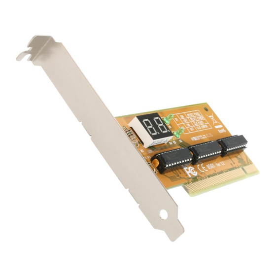
PCI POST PC System Diagnostics Test Card -
2 x 7 Segment LED
PCIPOST
DE: Bedienungsanleitung - de.startech.com
FR: Guide de l'utilisateur - fr.startech.com
ES: Guía del usuario - es.startech.com
IT: Guida per l'uso - it.startech.com
NL: Gebruiksaanwijzing - nl.startech.com
PT: Guia do usuário - pt.startech.com
For the most up-to-date information, please visit: www.startech.com
Manual Revision: 02/09/2012
*actual product may vary from photos
Advertisement
Table of Contents

Related Manuals for StarTech.com PCIPOST


Summary of Contents for StarTech.com PCIPOST
- Page 1 DE: Bedienungsanleitung - de.startech.com FR: Guide de l'utilisateur - fr.startech.com ES: Guía del usuario - es.startech.com IT: Guida per l'uso - it.startech.com NL: Gebruiksaanwijzing - nl.startech.com PT: Guia do usuário - pt.startech.com For the most up-to-date information, please visit: www.startech.com Manual Revision: 02/09/2012...
- Page 2 StarTech.com. Where they occur these references are for illustrative purposes only and do not represent an endorsement of a product or service by StarTech.com, or an endorsement of the product(s) to which this manual applies by the third-party company in question. Regardless of any direct acknowledgement elsewhere in the body of this document, StarTech.com hereby...
-
Page 3: Table Of Contents
Table of Contents Introduction ....................1 Packaging Contents ..........................1 Features ................................ 1 Before You Begin ............................2 Installation ....................2 Using Your Card............................3 Quick Error Reference Guide ......................... 4 AMI BIOS POST Test Codes ..............5 AMI WinBIOS/HiFLEX 101094 ........................ 5 Runtime code is uncompressed in F000 shadow ram .............. -
Page 4: Introduction
PCI Post Card, eliminating unnecessary troubleshooting steps and preventing non-defective parts from being replaced. Backed by Lifetime Warranty and free lifetime technical support, StarTech.com’s PCI Post card is designed and constructed to provide reliable computer diagnostics. Please Note: You may have to refer to your motherboard manufacturer’s manual for motherboard specific error diagnostic codes when using the PCI Post card. -
Page 5: Before You Begin
BIOS version. Without this information, you will not be able to determine the meaning of the error code. The PCIPOST card does not generate the error codes, the codes are generated by the BIOS supplier and are specific to that BIOS. Contact your motherboard manufacturer if you encounter any difficulties. -
Page 6: Using Your Card
5. Secure the card in place using the screw you removed in Step 3. 6. When you are ready to begin the test, plug your system in and turn it on. Using Your Card When power is first supplied to your computer, the power supply will generate a power good signal that is received by the motherboard clock if all the output voltages from the power supply are correct. -
Page 7: Quick Error Reference Guide
Quick Error Reference Guide Error BIOS (c) BIOS (c) Quadtel Caused 1990 Award Phoenix Troubleshooting 1994 AT BIOS HiFLEX WinBIOS BIOS Replace CPU 01~02 01~02 01~02 02~04 (speed should be the same) 1. Replace CPU Math 2. Replace CPU Comp- 9C~9D 9C~9D 76~78... -
Page 8: Ami Bios Post Test Codes
AMI BIOS POST Test Codes AMI WinBIOS/HiFLEX 101094 POST Code AMI WinBIOS uncompress code checkpoints description NMI is Disabled. Power on delay starting. Power on delay complete. Going to disable cache, is any. Calculating ROM BIOS checksum. ROM BIOS checksum passed. CMOS shutdown register test to be done next. CMOS shutdown register test done. -
Page 9: Runtime Code Is Uncompressed In F000 Shadow Ram
Runtime code is uncompressed in F000 shadow ram POST Code AMI HiFLES BIOS/WinBIOS runtime code description Processor register test about to start and NMI to be disabled. NMI is disabled. Power-on delay starting. Power on delay complete. To check soft reset/power-on. Soft reset/power-on determined. - Page 10 DMA controller #1, #2, interrupt controller #1, #2 disabled. Video display is disabled and port B is initialized. Chip set initialization about to begin. Chipset initialization over. 8254 timer test about to start. 8254 timer test over. About to start memory refresh test. Memory refresh line is toggling.
- Page 11 Display memory R/W test passed. About to look for the retrace checking. Display memory R/W test or retrace checking failed. About to alternate Display memory R/W test. Alternate Display memory R/W test passed. About to look for the alternate display retrace checking. Video display checking over.
- Page 12 Amount of memory above 1M found and verified. Check for soft reset and going to clear memory below 1M for soft reset. Memory below 1M cleared. Going to clear memory above 1M. Memory above 1M cleared. Going to save memory size. Memory test started.
- Page 13 Keyboard test started. Clearing output buffer and checking for stuck key. About to issue keyboard reset command. Keyboard reset error/stuck key found. About to issue keyboard controller interface test command. Keyboard controller interface test over. About to write command byte and initialize circular buffer.
- Page 14 Going to do any initialization before C800 optional ROM control. Any initialization before C800 optional ROM control is over. Optional ROM check and control will be done next. Optional ROM control is done. About to give control to do any required processing after optional ROM returns control.
- Page 15 Returned from E000 ROM control. Going to do any initialization required after E000 optional ROM control. Initialization after E000 optional ROM control is over. Going to display the system configuration. System configuration is displayed. Going to copy any code to specific area. Copying of code to specific area done.
- Page 16 While control is inside the different BUS routine, additional checkpoints are outputted to port 80h as WORD to identify the routines under execution. These are WORD checkpoints: the LOW BYTE of the checkpoint is the system BIOS checkpoint from where the control is passed to the different BUD routines and the HIGH BYTE of the checkpoint is the identification of which the routine is being executed in the different BUSes.
-
Page 17: Award Bios Post Test Code Listing
AWARD BIOS POST Test Code Listing Post Code Award POST Routine Description Turn off chipset cache. Test processor flag register. Test all processor registers except SS, SP and BP with pattern FF and Initialize Chips (RTC, 8254, 8237, 8259), reset math coprocessor, clear CMOS shutdown byte and page register. - Page 18 Test Timer 0 counter 2 Test 8259-1 interrupt mask register (port 21H) Test 82592 interrupt mask register (port A1H) Test stuck 8259’s interrupt bits. Test 8259 interrupt functionality. Test stuck NMI bits (verify NMI can be cleared). Display CPU clock. Set EISA mode.
- Page 19 Initialize time value in 40h; BIOS area. Setup virus protection according to setup. Set system speed for boot. Setup NumLock status according to setup. Boot attempt (set low stack, and boot via INT 19H). Spurious (if interrupt occurs in protected mode). Unclaimed NMI (if NMI occurs, press F1 to disable NMI, F2 for reboot).
-
Page 20: Phoenix Bios Post Test Code Listing
Phoenix BIOS POST Test Code Listing POST Code Phoenix POST Routine Description Verify real mode. Get CPU type. Initialize system hardware. Initialize chipset register with initial POST value. Set in POST flag. Initialize CPU register. Initialize cache to initial POST values. Initialize I/O CPU register. - Page 21 Test CPU BUS-clock frequency. Test CMOS RAM. Initialize alternate chipset registers. Reinitialize the chipset. Shadow system BIOS RAM. Reinitialize the cache. Autosize cache. Configure advanced chipset registers. Load alternate registers with CMOS values. Set initial CPU speed. Initialize interrupt vectors. Initialize BIOS interrupts.
- Page 22 Test RAM between 512 to 640K. Test extended memory. Test extended memory lines. Jump to UserPatch1. Configure advanced cache registers. Enable external and CPU cache. Display external cache size. Display shadow message. Display non-disposable segments. Display error messages. Check for configuration errors. Test real-time clock.
- Page 23 Disable A20 address line. Clear huge ES segment register. Search for option ROMs. Shadow option ROMs. Setup power management. Enable hardware interrupts. Set time of day. Check key lock. Initialize typematic rate. Ease F2 prompt. Scan for F2 stroke. Enter SETUP. Clear in-POST flag.
- Page 24 Extended BLOCK move. Shutdown 10 error. The following are for boot block in Flash ROM POST Code Pheonix POST Routine Description Initialize the chipset. Initialize refresh counter. Check for forced Flash. Check H/W status ROM. BIOS ROM is OK. Do a complete RAM test. Do OEM initialization.
-
Page 25: Technical Support
Limitation of Liability In no event shall the liability of StarTech.com Ltd. and StarTech.com USA LLP (or their officers, directors, employees or agents) for any damages (whether direct or indirect, special, punitive, incidental, consequential, or otherwise), loss of profits, loss of business, or any pecuniary loss, arising out of or related to the use of the product exceed the actual price paid for the product. - Page 26 StarTech.com is an ISO 9001 Registered manufacturer of connectivity and technology parts. StarTech.com was founded in 1985 and has operations in the United States, Canada, the United Kingdom and Taiwan servicing a worldwide market.
Need help?
Do you have a question about the PCIPOST and is the answer not in the manual?
Questions and answers