Yamaha TT-R125E Owner's Manual
Hide thumbs
Also See for TT-R125E:
- Owner's service manual (617 pages) ,
- Owner's manual (248 pages) ,
- Owner's service manual (610 pages)
Table of Contents
Advertisement
Read this manual carefully before operating this vehicle.
Il convient de lire attentivement ce manuel avant la première
utilisation du véhicule.
Bitte lesen Sie diese Bedienungsanleitung sorgfalfig durch,
bevor Sie das Fahrzeug in Betrieb nehmen.
OWNER´S MANUAL
MANUEL DU PROPRIÉTAIRE
BEDIENUNGSANLEITUNG
TT-R125E(A)
TT-R125LW(A)
TT-R125LWE(A)
39C-F8199-81
Advertisement
Table of Contents
Troubleshooting

Related Manuals for Yamaha TT-R125E


Summary of Contents for Yamaha TT-R125E
- Page 1 Read this manual carefully before operating this vehicle. Il convient de lire attentivement ce manuel avant la première utilisation du véhicule. Bitte lesen Sie diese Bedienungsanleitung sorgfalfig durch, bevor Sie das Fahrzeug in Betrieb nehmen. OWNER´S MANUAL MANUEL DU PROPRIÉTAIRE BEDIENUNGSANLEITUNG TT-R125E(A) TT-R125LW(A) TT-R125LWE(A) 39C-F8199-81...
- Page 2 YAMAHA MOTOR DA AMAZÔNIA LTDA. PRINTED IN BRAZIL IMANAM 05,2010 (E,F,G)
- Page 3 Read this manual carefully before operating this vehicle. OWNER´S MANUAL TT-R125E( ) TT-R125LW( ) TT-R125LWE( ) 39C-F8199-81-E0...
- Page 4 EAUW2210 Read this manual carefully before operating this vehicle. This manual should stay with this vehicle if it is sold.
- Page 5 Yamaha has met these standards without reducing the performance or economy of operation of the motorcycle. To maintain these high standards, it is important that you and your Yamaha dealer pay close attention to the recommended maintenance schedules and operating instructions contained within this manual.
- Page 6 INTRODUCTION Weight of the rider should not exceed TT-R125E 68.0 kg (150 lb). AN IMPORTANT NOTE TO PARENTS: This motorcycle is not a toy. Before you let your child ride this motorcycle, you should understand the instructions and warn- ings in this Owner’s Manual. Then be sure your child understands and will follow them. Children differ in skills, physical abil- ities, and judgment.
-
Page 7: Important Manual Information
IMPORTANT MANUAL INFORMATION EAU10132 Particularly important information is distinguished in this manual by the following notations: This is the safety alert symbol. It is used to alert you to potential personal injury hazards. Obey all safety messages that follow this symbol to avoid possible injury or death. - Page 8 IMPORTANT MANUAL INFORMATION EAUW0011 TT-R125E/TT-R125LW/TT-R125LWE OWNER’S MANUAL ©2010 by Yamaha Motor da Amazônia Ltda. 1st edition, May 2010 All rights reserved. Any reprinting or unauthorized use without the written permission of Yamaha Motor da Amazônia Ltda. is expressly prohibited. Printed in Brazil.
-
Page 9: Table Of Contents
TABLE OF CONTENTS LOCATION OF IMPORTANT FOR YOUR SAFETY – Adjusting the clutch lever free LABELS ..........1-1 PRE-OPERATION CHECKS ..... 5-1 play ........... 7-16 Adjusting the brake lever free SAFETY INFORMATION ....2-1 OPERATION AND IMPORTANT play ........... 7-17 RIDING POINTS ........ 6-1 Adjusting the brake lever free DESCRIPTION ........3-1 Starting a cold engine .... - Page 10 TABLE OF CONTENTS Replacing the fuse ......7-29 Supporting the motorcycle ....7-29 Front wheel ........7-30 Rear wheel ........7-32 Troubleshooting ......7-34 Troubleshooting chart ....7-35 MOTORCYCLE CARE AND STORAGE ..........8-1 Care ..........8-1 Storage ...........8-3 SPECIFICATIONS ......9-1 CONSUMER INFORMATION...10-1 Identification numbers ....10-1...
-
Page 11: Location Of Important Labels
Read and understand all of the labels on your vehicle. They contain important information for safe and proper operation of your vehicle. Never remove any labels from your vehicle. If a label becomes difficult to read or comes off, a replacement label is available from your Yamaha dealer. For Canada... - Page 12 LOCATION OF IMPORTANT LABELS For Canada...
- Page 13 LOCATION OF IMPORTANT LABELS For Canada...
- Page 14 LOCATION OF IMPORTANT LABELS For Europe...
- Page 15 LOCATION OF IMPORTANT LABELS For Europe...
- Page 16 LOCATION OF IMPORTANT LABELS Familiarize yourself with the following pictograms and read the explanatory text. Read the Owner’s manual. Use unleaded gasoline only. This unit contains high-pressure Measure the tire pressure when nitrogen gas. the tires are cold. Mishandling can cause an explosion.
- Page 17 LOCATION OF IMPORTANT LABELS Model Name ****** Max. Power *** kW *** kg Mass In Running Order 1 Year of construction **** YAMAHA MOTOR CO., LTD. 2500 SHINGAI, IWATA, JAPAN...
- Page 18 LOCATION OF IMPORTANT LABELS For Oceania and South Africa...
- Page 19 LOCATION OF IMPORTANT LABELS For Oceania and South Africa...
-
Page 20: Safety Information
SAFETY INFORMATION EAU41219 Safe Riding yourself conspicuous appears to Perform the pre-operation checks each be very effective in reducing the time you use the vehicle to make sure it chance of this type of accident. Be a Responsible Owner is in safe operating condition. Failure to Therefore: As the vehicle’s owner, you are respon- inspect or maintain the vehicle properly... - Page 21 SAFETY INFORMATION Many accidents have been caused Protective Apparel Avoid Carbon Monoxide Poisoning by error of the motorcycle opera- The majority of fatalities from motorcy- All engine exhaust contains carbon tor. A typical error made by the op- cle accidents are the result of head in- monoxide, a deadly gas.
- Page 22 Adding accessories to your motorcycle motorcycle before riding. mended by Yamaha, even if sold and can adversely affect stability and han- Check accessory mounts fre- installed by a Yamaha dealer. dling if the weight distribution of the mo- quently.
-
Page 23: Specifications
SAFETY INFORMATION Never install accessories that tor and may limit control ability, Check that the fuel cock (if would impair the performance of therefore, such accessories are equipped) is in the “OFF” position your motorcycle. Carefully inspect not recommended. and that there are no fuel leaks. the accessory before using it to Use caution when adding electri- Point the front wheel straight... -
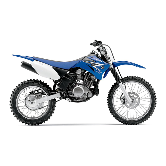
Page 24: Description
DESCRIPTION EAU32220 Left view TT-R125E 1. Fuel cock (page 4-6) 2. Spark arrester (page 7-11) 3. Shock absorber assembly spring preload adjusting nut (page 4-8) 4. Shift pedal (page 4-2) - Page 25 DESCRIPTION TT-R125LW/TT-R125LWE 1. Fuel cock (page 4-6) 2. Spark arrester (page 7-11) 3. Shock absorber assembly spring preload adjusting nut (page 4-8) 4. Shift pedal (page 4-2)
-
Page 26: Right View
DESCRIPTION EAU32230 Right view TT-R125E 1. Air filter element (page 7-10) 8. Brake pedal (page 4-3) 2. Battery (page 7-27) 3. Fuse (page 7-29) 4. Kickstarter (page 4-7) 5. Throttle stop screw (page 7-13) 6. Fuel tank (page 4-3) 7. Engine oil filler cap (page 7-8) - Page 27 DESCRIPTION TT-R125LW/TT-R125LWE 1. Air filter element (page 7-10) 2. Battery (page 7-27) 3. Fuse (page 7-29) 4. Kickstarter (page 4-7) 5. Throttle stop screw (page 7-13) 6. Fuel tank (page 4-3) 7. Engine oil filler cap (page 7-8) 8. Brake pedal (page 4-3)
-
Page 28: Controls And Instruments
DESCRIPTION EAU10430 Controls and instruments 1. Clutch lever (page 4-2) 2. Engine stop switch (page 4-1) 3. Main switch (page 4-1) 4. Starter (choke) knob (page 4-6) 5. Start switch (page 4-1) 6. Front brake lever (page 4-3) 7. Throttle grip (page 7-13) 8. -
Page 29: Instrument And Control Functions
INSTRUMENT AND CONTROL FUNCTIONS EAU40340 EWA10072 EAU12348 Main switch Handlebar switches WARNING Never turn the key to “OFF” while Left the vehicle is moving, otherwise the electrical systems will be switched off, which may result in loss of con- trol or an accident. The main switch controls the ignition 1. -
Page 30: Clutch Lever
INSTRUMENT AND CONTROL FUNCTIONS EAU12670 EAU31640 EAU12871 “ENGINE STOP” button Clutch lever Shift pedal Hold this button pushed until the engine stops in case of an emergency, such as when the vehicle overturns or when the throttle cable is stuck. EAU12711 Start switch “... -
Page 31: Brake Lever
INSTRUMENT AND CONTROL FUNCTIONS EAU12890 EAU12941 EAU13182 Brake lever Brake pedal Fuel tank cap 1. Front brake lever 1. Brake pedal 1. Fuel tank cap The brake lever is located at the right The brake pedal is on the right side of To remove the fuel tank cap, turn it handlebar grip. -
Page 32: Fuel
Handle gaso- heat from the engine or the sun line with care. Never siphon gaso- Your Yamaha engine has been de- can cause fuel to spill out of the line by mouth. If you should swallow signed to use regular unleaded gaso- fuel tank. -
Page 33: Fuel Tank Breather Hose
There are two types of gasohol: gaso- as well as to the exhaust system. hol containing ethanol and that contain- Your Yamaha engine has been de- ing methanol. Gasohol containing signed to use regular unleaded gaso- ethanol can be used if ethanol content line with a research octane number of does not exceed 10% (E10). -
Page 34: Fuel Cock
INSTRUMENT AND CONTROL FUNCTIONS EAU13561 EAU13600 Fuel cock Starter (choke) knob “ ” This indicates reserve. If you run out of The fuel cock supplies fuel from the fuel while riding, move the lever to this tank to the carburetor while filtering it al- position. -
Page 35: Kickstarter
INSTRUMENT AND CONTROL FUNCTIONS EAU13660 EAUW0482 Kickstarter Seat To remove the seat 1. Remove panel A. (See page 7-6.) 2. Remove the bolt. 3. Remove the bolt that fastens the seat and panel C. 4. Remove the seat by pulling it off. 2. -
Page 36: Adjusting The Front Fork
INSTRUMENT AND CONTROL FUNCTIONS EAU14722 EAUW0475 Adjusting the front fork Adjusting the shock absorber EWA10180 assembly WARNING This shock absorber assembly is Always adjust both fork legs equal- equipped with a spring preload adjust- ly, otherwise poor handling and loss ing nut, a rebound damping force ad- of stability may result. - Page 37 INSTRUMENT AND CONTROL FUNCTIONS (a). To decrease the rebound damping Spring preload: force and thereby soften the rebound Minimum (soft) for TT-R125E/TT- damping, turn the adjusting dial in di- R125LW: Distance A = 175 mm (6.89 in) rection (b). Minimum (soft) for TT-R125LWE: Distance A = 167.5 mm (6.59 in)
-
Page 38: Sidestand
To obtain a precise adjustment, it is ad- sembly yourself. Take the shock in a possible loss of control. visable to check the actual total number absorber assembly to a Yamaha of clicks or turns of the damping force dealer for any service. adjusting mechanism. This adjustment... -
Page 39: Starting Circuit Cut-Off System
INSTRUMENT AND CONTROL FUNCTIONS EAU15391 Starting circuit cut-off system The starting circuit cut-off system (com- prising the clutch switch and the neutral switch) prevents starting when the transmission is in gear and the clutch lever is not pulled. Periodically check the operation of the starting circuit cut-off system according to the following procedure. - Page 40 With the engine turned off: 1. Make sure that the engine stop switch is set to “ ”. If a malfunction is noted, have a Yamaha 2. Turn the key to “ON”. dealer check the system before riding. 3. Shift the transmission into the neutral position.
-
Page 41: For Your Safety - Pre-Operation Checks
• If necessary, add recommended oil to specified level. • Check vehicle for oil leakage. • Check operation. • If soft or spongy, have Yamaha dealer bleed hydraulic system. • Check lever free play. • Adjust if necessary. Front brake •... - Page 42 • Make sure that operation is smooth. • Check cable free play. Throttle grip 7-13, 7-24 • If necessary, have Yamaha dealer adjust cable free play and lubricate cable and grip housing. • Make sure that operation is smooth. Control cables 7-24 •...
-
Page 43: Operation And Important Riding Points
Yamaha dealer. The transmission is in the neutral 6. When the engine is warm, turn the position. -
Page 44: Starting A Warm Engine
OPERATION AND IMPORTANT RIDING POINTS EAU16640 EAU16671 ECA10260 Starting a warm engine Shifting NOTICE Follow the same procedure as for start- Even with the transmission in ing a cold engine with the exception the neutral position, do not that the starter (choke) is not required coast for long periods of time when the engine is warm. -
Page 45: Engine Break-In
To allow the engine If any engine trouble should occur is almost completely stopped. to cool down from the temporary build- during the engine break-in period, up of heat, cruise at a lower engine immediately have a Yamaha dealer speed. check the vehicle. -
Page 46: Parking
OPERATION AND IMPORTANT RIDING POINTS EAU17171 Parking When parking, stop the engine, remove the key from the main switch, and then turn the fuel cock lever to “OFF”. EWA10311 WARNING Since the engine and exhaust system can become very hot, park in a place where pedestri- ans or children are not likely to touch them and be burned. -
Page 47: Periodic Maintenance And Adjustment
To avoid possible burns, let tivities incorrectly may increase brake components cool before your risk of injury or death during touching them. service or while using the vehicle. If you are not familiar with vehicle ser- vice, have a Yamaha dealer perform service. -
Page 48: Periodic Maintenance Chart For The Emission Control System
From 7000 km (4200 mi) or 18 months, repeat the maintenance intervals starting from 3000 km (1800 mi) or 6 months. Items marked with an asterisk should be performed by a Yamaha dealer as they require special tools, data and technical skills. -
Page 49: General Maintenance And Lubrication Chart
From 7000 km (4200 mi) or 18 months, repeat the maintenance intervals starting from 3000 km (1800 mi) or 6 months. Items marked with an asterisk should be performed by a Yamaha dealer as they require special tools, data and technical skills. - Page 50 9 * Swingarm pivot bearings • Moderately repack with lithium-soap-based grease. • Check chain slack/alignment and condition. Drive chain • Adjust and lubricate chain with Yamaha chain and cable Every ride lube thoroughly. • Check bearing assemblies for looseness. √...
- Page 51 √ • Check operation. Rear suspension link piv- 21 * √ • Lubricate with lithium-soap-based grease. • Apply Yamaha chain and cable lube or engine oil thor- √ √ √ 22 * Control cables oughly. • Check operation and free play.
-
Page 52: Removing And Installing Panels
PERIODIC MAINTENANCE AND ADJUSTMENT EAU18771 To install the panel Removing and installing pan- Place the panel in the original position, and then install the quick fastener. The panels shown need to be removed to perform some of the maintenance EAU19193 Panel B jobs described in this chapter. -
Page 53: Checking The Spark Plug
Clean the surface of the spark plug such problems yourself. Instead, have gasket and its mating surface, and then a Yamaha dealer check the vehicle. wipe off any grime from the spark plug If the spark plug shows signs of elec- threads. -
Page 54: Engine Oil
PERIODIC MAINTENANCE AND ADJUSTMENT EAUW0432 tank cap. NOTICE: Do not [EWA10361] Engine oil operate the vehicle until you The engine oil level should be checked know that the engine oil level is before each ride. In addition, the oil sufficient. [ECA10011] must be changed at the intervals spec- ified in the periodic maintenance and... - Page 55 (since the engine oil also off immediately and consult a lubricates the clutch), do not mix any chemical additives. Do Yamaha dealer for inspection. not use oils with a diesel speci- fication of “CD” or oils of a high- er quality than specified. Make sure that the engine oil doesn’t...
-
Page 56: Cleaning The Air Filter Element And Check Hoses
5. Remove the sponge material from the air filter element frame. The sponge material should be wet but not dripping. Recommended oil: Yamaha foam air filter oil or other 1. Band quality foam air filter oil 2. Air filter case cover 7-10... -
Page 57: Cleaning The Spark Arrester
PERIODIC MAINTENANCE AND ADJUSTMENT 8. Install the sponge material onto 10. Install the air filter case cover by in- EAUW0450 Cleaning the spark arrester the frame, place the air filter ele- stalling the band. The spark arrester should be cleaned ment in the original position on the 11. -
Page 58: Adjusting The Carburetor
Therefore, most car- buretor adjustments should be left to a Tightening torque: Yamaha dealer, who has the neces- Spark arrester cap bolt: 10 Nm (1.0 m·kgf, 7.2 ft·lbf) sary professional knowledge and expe- rience. -
Page 59: Adjusting The Engine Idling Speed
The engine idling speed must be cor- sponds to the throttle. Yamaha dealer make the adjustment. rectly adjusted before checking and ad- 3. Check the engine idling speed justing the throttle cable free play. -
Page 60: Valve Clearance
(b). from occurring, the valve clearance the specified tires. must be adjusted by a Yamaha dealer at the intervals specified in the periodic Tire air pressure maintenance and lubrication chart. The tire air pressure should be checked and, if necessary, adjusted before each ride. - Page 61 PERIODIC MAINTENANCE AND ADJUSTMENT glass fragments in it, or if the sidewall is Front: Front tire: cracked, have a Yamaha dealer re- 100 kPa (1.00 kgf/cm², 15 psi) Size: place the tire immediately. Rear: TT-R125E 70/100-17 40M 100 kPa (1.00 kgf/cm², 15 psi)
-
Page 62: Spoke Wheels
10.0–15.0 mm (0.39–0.59 in) as age before each ride. If any dam- shown. Periodically check the clutch le- age is found, have a Yamaha ver free play and, if necessary, adjust it dealer replace the wheel. Do not as follows. -
Page 63: Adjusting The Brake Lever Free Play
1. Locknut 2. Brake lever free play adjusting nut 3. Brake lever free play The brake lever free play should mea- sure TT-R125E 10.0–15.0 mm (0.39– 0.59 in) TT-R125LW 2.0–5.0 mm (0.08–0.20 1. Locknut (clutch cable) 2. Clutch lever free play adjusting bolt TT-R125LWE 2.0–5.0 mm (0.08–0.20... -
Page 64: Adjusting The Brake Lever Free Play
6. To increase the brake lever free The brake lever free play should mea- play, turn the adjusting nut at the sure TT-R125E 10.0–15.0 mm (0.39– brake shoe plate in direction (a). 0.59 in) To decrease the brake lever free TT-R125LW 2.0–5.0 mm (0.08–0.20... -
Page 65: Adjusting The Brake Pedal Position And Free Play
WARNING draulic system, have a Yamaha To increase the brake pedal free play, It is advisable to have a Yamaha dealer bleed the system before turn the adjusting nut at the brake rod in dealer make these adjustments. -
Page 66: Checking The Front Brake Shoes
2. Brake shoe wear limit line thickness is less than 0.8 mm (0.03 in), After adjusting the drive chain have a Yamaha dealer replace the The front brake shoes must be checked slack or removing and installing brake pads as a set. -
Page 67: Checking The Front Brake Fluid Level
Be careful that water does not en- and/or brake system leakage. If the the wear limit line, have a Yamaha ter the master cylinder when refill- brake fluid level is low, be sure to check dealer replace the brake shoes as a ing. -
Page 68: Changing The Brake Fluid
Brake fluid may deteriorate paint- EAU22721 EAU22760 Changing the brake fluid Drive chain slack ed surfaces or plastic parts. Al- Have a Yamaha dealer change the The drive chain slack should be ways clean spilled fluid brake fluid at the intervals specified in checked before each ride and adjusted immediately. - Page 69 PERIODIC MAINTENANCE AND ADJUSTMENT of the motorcycle and can lead 5. Adjust the brake pedal free play. to chain slippage or breakage. (See page 7-19.) To prevent this from occurring, keep the drive chain slack with- in the specified limits. [ECA10571] Make sure that both adjusting plates are in the same position for proper...
-
Page 70: Cleaning And Lubricating The Drive Chain
Yamaha dealer at the intervals speci- out, especially when riding in dusty or ed if necessary. If a cable is damaged fied in the periodic maintenance chart. -
Page 71: Checking And Lubricating The Brake And Shift Pedals
PERIODIC MAINTENANCE AND ADJUSTMENT EAU44272 EAU43611 Recommended lubricant: Checking and lubricating the Checking and lubricating the Lithium-soap-based grease brake and shift pedals brake and clutch levers Brake pedal Brake lever The operation of the brake and shift Clutch lever pedals should be checked before each ride, and the pedal pivots should be lu- bricated if necessary. -
Page 72: Checking And Lubricating The Sidestand
WARNING! To avoid injury, have a Yamaha dealer check or re- sidestand pivot and metal-to-metal securely support the vehicle so pair it. -
Page 73: Checking The Steering
(Valve Regulated Lead Acid) battery. ward and backward. If any free There is no need to check the electro- play can be felt, have a Yamaha lyte or to add distilled water. However, dealer check or repair the steering. the battery lead connections need to be checked and, if necessary, tightened. - Page 74 To charge the battery burns. Avoid any contact with once a month and fully charge it if Have a Yamaha dealer charge the bat- skin, eyes or clothing and al- necessary. tery as soon as possible if it seems to ways shield your eyes when 3.
-
Page 75: Replacing The Fuse
4. If the fuse immediately blows right. Check that the motorcycle is in a again, have a Yamaha dealer stable and level position before starting check the electrical system. any maintenance. A strong wooden box can be placed under the engine for added stability. -
Page 76: Front Wheel
Front wheel frame in front of the rear wheel or under each side of the swingarm. EAUW0532 To remove the front wheel (TT-R125E) EWA10821 WARNING To avoid injury, securely support the vehicle so there is no danger of it falling over. - Page 77 7. Remove the wheel and the brake (TT-R125LW/TT-R125LWE) shoe plate. EWA10821 WARNING EAUW0550 To install the front wheel (TT-R125E) To avoid injury, securely support the 1. Slot 1. Install the brake shoe plate into the vehicle so there is no danger of it 2. Retainer wheel.
-
Page 78: Rear Wheel
PERIODIC MAINTENANCE AND ADJUSTMENT EAU25080 Rear wheel Make sure that there is enough space between the brake pads before insert- EAU25421 To remove the rear wheel ing the brake disc into the caliper. EWA10821 WARNING 2. Insert the wheel axle, and then in- stall the washer and axle nut. - Page 79 PERIODIC MAINTENANCE AND ADJUSTMENT 4. Lift the rear wheel off the ground according to the procedure on page 7-29. 5. Remove the axle nut, and then pull the wheel axle out. 6. Push the wheel forward, and then remove the drive chain from the rear sprocket.
-
Page 80: Troubleshooting
However, should your motorcycle require any repair, take it to a Yamaha dealer, whose skilled technicians have the necessary tools, experience, and know-how to service the motorcycle properly. -
Page 81: Troubleshooting Chart
Remove the spark plug and check the electrodes. The engine does not start. Have a Yamaha dealer check the vehicle. Check the battery. 4. Battery The engine turns over The battery is good. -
Page 82: Motorcycle Care And Storage
MOTORCYCLE CARE AND STORAGE EAU41356 ucts onto seals, gaskets, sprock- off any detergent residue using Care ets, the drive chain and wheel plenty of water, as it is harmful While the open design of a motorcycle axles. Always rinse the dirt and de- to plastic parts. - Page 83 MOTORCYCLE CARE AND STORAGE Test the product on a small hid- 2. Apply a corrosion protection spray EWA11131 WARNING den part of the windshield to on all metal, including chrome- and make sure that it does not leave nickel-plated, surfaces to prevent Contaminants on the brakes or tires any marks.
-
Page 84: Storage
MOTORCYCLE CARE AND STORAGE EAU26152 2. For motorcycles equipped with a Storage fuel cock that has an “OFF” posi- Consult a Yamaha dealer for advice on tion: Turn the fuel cock lever to what products to use. Short-term “OFF”. Always store your motorcycle in a cool, 3. - Page 85 MOTORCYCLE CARE AND STORAGE WARNING! To prevent dam- cessively cold or warm place [less age or injury from sparking, than 0 °C (30 °F) or more than 30 make sure to ground the °C (90 °F)]. For more information spark plug electrodes while on storing the battery, see page turning the engine over.
-
Page 86: Specifications
Weight: Compression ratio: 10.00 :1 Overall length: With oil and fuel: Starting system: TT-R125E 1845 mm (72.6 in) TT-R125E 90 kg (198 lb) TT-R125E Electric starter and kickstarter TT-R125LW 1885 mm (74.2 in) TT-R125LW 84 kg (185 lb) TT-R125LW Kickstarter TT-R125LWE 1885 mm (74.2 in) - Page 87 Loading: Spark plug gap: Caster angle: 0.6–0.7 mm (0.024–0.028 in) Maximum rider weight: TT-R125E 28.70 ° Clutch: TT-R125E 68.0 kg (150 lb) TT-R125LW 28.50 ° Tire air pressure (measured on cold Clutch type: TT-R125LWE 28.50 ° Wet, multiple-disc tires): Trail:...
- Page 88 SPECIFICATIONS Rim size: Wheel travel: TT-R125E 14x1.60 TT-R125E 160.0 mm (6.30 in) TT-R125LW 16x1.60 TT-R125LW 168.0 mm (6.61 in) TT-R125LWE 16x1.60 TT-R125LWE 168.0 mm (6.61 in) Front brake: Electrical system: Type: Ignition system: TT-R125E Drum brake TT-R125LW Single disc brake...
-
Page 89: Consumer Information
Record the vehicle identification num- ber and model label information in the spaces provided below for assistance when ordering spare parts from a Yamaha dealer or for reference in case the vehicle is stolen. VEHICLE IDENTIFICATION NUMBER: 1. Vehicle identification number 1. - Page 90 CONSUMER INFORMATION EAU48120 Vehicle Emission Control Informa- tion label (For Canada) 1. Vehicle Emission Control Information label The Vehicle Emission Control Informa- tion label is affixed at the location in the illustration. This label shows specifica- tions related to exhaust emissions as required by federal law, state law and Environment Canada.
- Page 91 INDEX Spark plug, checking ......7-7 Specifications.......... 9-1 Air filter element and check hoses, Front fork, adjusting ........4-8 Starter (choke) knob ....... 4-6 cleaning ..........7-10 Front fork, checking.......7-26 Starting a cold engine ......6-1 Fuel ............4-4 Starting circuit cut-off system....4-11 Fuel cock..........4-6 Battery ..........
- Page 92 YAMAHA MOTOR DA AMAZÔNIA LTDA. P RINTED IN BRAZIL 2 0 0...
Need help?
Do you have a question about the TT-R125E and is the answer not in the manual?
Questions and answers