Table of Contents
Advertisement
This manual is to be used by qualified appliance
technicians only. Maytag does not assume any
responsibility for property damage or personal
injury for improper service procedures done by
an unqualified person.
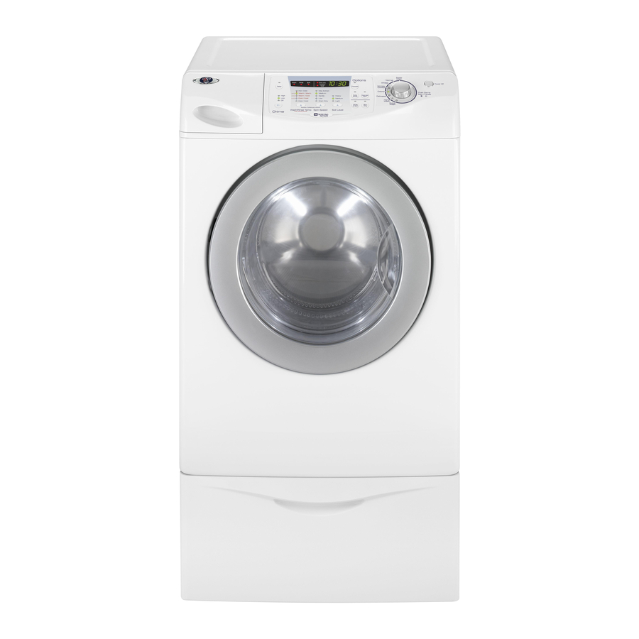
27" Front Load
Washer
This Base Manual covers general information.
Refer to individual Technical Sheet
for information on specific models.
This manual includes, but is
not limited to the following:
MAH8700AW*
16026126
March 2005
©2005 Maytag Services
Advertisement
Table of Contents
Troubleshooting

Related Manuals for Maytag MAH8700AW*


Summary of Contents for Maytag MAH8700AW*
- Page 1 Service This manual is to be used by qualified appliance technicians only. Maytag does not assume any responsibility for property damage or personal injury for improper service procedures done by an unqualified person. 27” Front Load Washer This Base Manual covers general information.
-
Page 2: Important Information
Important Notices for Servicers and Consumers Maytag will not be responsible for personal injury or property damage from improper service procedures. Pride and workmanship go into every product to provide our customers with quality products. It is possible, however, that during its lifetime a product may require service. -
Page 3: Table Of Contents
Boot Removal ............32 Heater Removal ............32 Motor Removal ............33 Drain Pump Removal ..........35 Outer Tub/Spinner Removal ........36 Appendix A Installation Instructions ..........41 Appendix B Use And Care ............49 ©2005 Maytag Services 16026126 Rev. 0... -
Page 4: Important Safety Information
Important Safety Information when required. Do not do it yourself unless you know how! • To reduce the risk of fire, clothes which have traces To reduce the risk of fire, electric shock, serious injury of any flammable substances such as vegetable oil, or death to persons when using your washer, follow cooking oil, machine oil, flammable chemicals, these basic precautions:... - Page 5 About Ground Wires Important Safety Information In the event of an electrical short circuit, a ground wire reduces the risk of electric shock by providing an escape wire for the electric current. Standard accepted color coding for ground wires is green To avoid personal injury or death from improper servicing, or green with a yellow stripe.
- Page 6 Important Safety Information Explanation Polarization–This means that the larger slot must be neutral and the small slot must be at line voltage. Mispolarized–The outlet is incorrectly wired so that the larger slot is at line voltage and the smaller slot is neutral. Grounded–This means the round hole connection is con- nected to earth ground through a connection to the main power panel.
- Page 7 Important Safety Information 16026126 Rev. 0 ©2005Maytag Services...
-
Page 8: General Information Model Identification
• For Maytag product call 1-800-688-9900 or visit the technician: Web Site at www.maytag.com • For Maytag call 1-800-462-9824 or visit the Web Site at • For product in Canada call 1-866-587-2002 or visit the www.maytag.com. Web Site at www.maytag.com. -
Page 9: Washer Nomenclature
General Information Washer Nomenclature Color Brand White Platinum M= Maytag Product Type Listing 120V-60hz AH= Automatic 240V-60hz Horizontal Canada 240V-60hz 220-240 V / 50-60 Hz Marketing Code Feature Content This identifies which 9700 Feature Package version of production the unit is. -
Page 10: Troubleshooting Procedures
Towel loads have a Pins 1 & 2 = 11.6ohms ±7%, minimal amount of soil present and typically Pins 2 & 3 = 11.6 ohms ±7% • Check belt. • Faulty Main Control Board. 16026126 Rev. 0 ©2005 Maytag Services... - Page 11 LO is displayed, Main Control Board and Door Lock Switch should be checked. • Place washer into Service Mode and check for diagnostic codes 4,18 & 22.. • Check electrical connections at lock switch ©2005 Maytag Services 16026126 Rev. 0...
- Page 12 Low Water level reset Door switch is within 15 read as open and minutes, before a the door locked spin begins. switch is read as locked. 16026126 Rev. 0 ©2005 Maytag Services...
- Page 13 Press Off (also variety of special service tests and view diagnostic Temperature exits Service Service displays. and Soil Level Mode) Cycle Enter / Exit Service Mode To enter Service Mode press the Chime and Extra ©2005 Maytag Services 16026126 Rev. 0...
- Page 14 Release Rotary Cycle Count Rotary Selector No. for Selector, while (returns to Diagnostic diagnostic code diagnostic code Code is displayed display) Press Delay Clear All and Chime Diagnostic together while Codes displaying diagnostic codes 16026126 Rev. 0 ©2005 Maytag Services...
- Page 15 When the “Rotary Cycle Selector” is set to “Whites ”and the “Rotary Cycle Selector” is pressed, the High water level will be – – displayed: “ 0” if below level, “ 1” if above ©2005 Maytag Services 16026126 Rev. 0...
- Page 16 “ 1” if Whites. Press above level. Rotary Selector Knob. Rotary cycle Medium “ ” if below —0 selector set to water level level. “—1” if Wrinkle Control. above level. Press Rotary Selector Knob. 16026126 Rev. 0 ©2005 Maytag Services...
- Page 17 This output will remain on until the “Rotary Cycle Selector” button is pressed again to turn off the output. The control will not allow the machine to fill past the High water level. ©2005 Maytag Services 16026126 Rev. 0...
- Page 18 Selector is pressed and held, the machine will display exceeding the number of cycles since the diagnostic code 400 rpm occurred. To clear the diagnostic list press the Delay and Chime keys for 3 seconds while viewing the list. 16026126 Rev. 0 ©2005 Maytag Services...
- Page 19 Will display "od" If seen open wash cycles. door open sensing, since the last Door switch will cleared. three final was not seen spins open since the last two final spins ©2005 Maytag Services 16026126 Rev. 0...
- Page 20 "3E".Check the Motor failure is detected. motor windings, the remaining in Service Mode. A power loss (Over Motor won't speed sensor, during Service Mode will cancel this mode. current) turn. wiring connections, or Control Board. 16026126 Rev. 0 ©2005 Maytag Services...
-
Page 21: Component Testing Information
Check voltage at Pin #1 and Pin #3 of 120V AC Check voltage at Pin #1 of CN5 and Pin #1 of CN6 120V AC Reactor Unplug harness connector and test from wire insertion side. Less than 1 ohm ©2005 Maytag Services 16026126 Rev. 0... - Page 22 To avoid risk of electrical shock, personal injury or death, disconnect power to unit before servicing, unless testing requires power. CN10 Motor Normal resistance is approximately 3.0? between any 2 pins (1,2 or 3 ) on motor connector. 16026126 Rev. 0 ©2005 Maytag Services...
- Page 23 Water flow through dispenser during Wash fill WASH WASH FILL / FILL / COOLING / COOLING / DRAIN DRAIN (HEATING) (HEATING) WASHING WASHING Rotation of Rotation of DISENTANGLE DISENTANGLE TOTAL TOTAL Spinner Spinner ©2005 Maytag Services 16026126 Rev. 0...
- Page 24 RINSE 1 DISENTANGLE DISENTANGLE FILL / FILL / MIDTERM MIDTERM / FILLING TO / FILLING TO DRAIN DRAIN RINSE RINSE Rotation of Rotation of SPIN SPIN REMOVE REMOVE TOTAL TOTAL Spinner Spinner SUDS SUDS 16026126 Rev. 0 ©2005 Maytag Services...
- Page 25 RINSE 2 FILL / FILL / DISENTANGLE DISENTANGLE MIDTERM MIDTERM DRAIN DRAIN RINSE RINSE Rotation of Rotation of / FILLING TO / FILLING TO SPIN SPIN TOTAL TOTAL Spinner Spinner REMOVE SUDS REMOVE SUDS ©2005 Maytag Services 16026126 Rev. 0...
-
Page 26: Disassembly Procedures Top Removal
Top Cover. Water Level Sensor Removal 1. Disconnect power supply to unit. 2. Remove Top Cover. 3. Remove harness plug. 4. Remove Pressure Hose. 5. Remove single attachment screw. 16026126 Rev. 0 ©2005 Maytag Services... -
Page 27: Reactor Removal
1. Disconnect power supply to unit. 2. Remove Top Cover. 3. Remove single attachment screw on cross brace. 4. Twist Reactor counterclockwise to remove. NOTE: Mark the wire locations on the EMI before removing the terminals. 16026126 Rev. 0 ©2005 Maytag Services... -
Page 28: Water Valve Removal
2. Depress the release tab and slide drawer from Main Main Bleach Cold washer. Wash NOTE: The hose circuitry is marked on the Dispenser top. 5. Remove attachment screws and lift dipenser to expose fill hose. 16026126 Rev. 0 ©2005 Maytag Services... -
Page 29: Console Removal
1. Disconnect power supply to unit. 2. Remove four screws to remove door from Front Panel. Console Removal 1. Disconnect power supply to unit. 2. Remove Top Cover. 3. Remove Dispenser Drawer. 4. Remove five screws attaching Console. 16026126 Rev. 0 ©2005 Maytag Services... -
Page 30: Disassembly Procedures
6. Remove the glass retainer. 3. Remove hinge retainer plate. 7. Remove glass. 4. Remove door from hinge posts. 8. Remove external viewing window. 5. Remove Screws around the perimeter of the glass retainer. 16026126 Rev. 0 ©2005 Maytag Services... -
Page 31: Front Panel Removal
Boot Clamp Spring located at the 6 o’clock position. 6. Remove four screws attaching the front to the cabinet. 7. Disconnect the wire connectors to the Door Lock. 5. Pull the boot from the lip formed into the front opening. 16026126 Rev. 0 ©2005 Maytag Services... -
Page 32: Boot Removal
3. Remove Console. 4. Remove Front Panel. 5. Loosen boot clamp at the 12 o’clock position. 6. Loosen 10mm nut on Heater and remove Heater Element. NOTE: Install Heater Element on top of metal bracket. 16026126 Rev. 0 ©2005 Maytag Services... -
Page 33: Motor Removal
1. Disconnect power supply to unit. 2. Remove two screws attaching Back Cover and slide cover up and lift bottom edge out of retaining slots. 4. Remove wire harness plug to motor and ground wire. 3. Remove Drive Belt. 16026126 Rev. 0 ©2005 Maytag Services... - Page 34 To avoid risk of electrical shock, personal injury or WARNING death; disconnect power to unit before servicing. 5. Remove two13mm bolts. 6. Remove Motor from Cabinet. NOTE: During reinstallation be sure all four bushings are installed properly 16026126 Rev. 0 ©2005 Maytag Services...
-
Page 35: Drain Pump Removal
3. Remove clamp and Drain Hose. 4. Remove clamp and Pump Hose. 6. Remove three 13mm bolts securing Drain Pump to base. 7. Remove screw securing Drain Pump to bracket. Twist Drain Pump clockwise to remove. 16026126 Rev. 0 ©2005 Maytag Services... - Page 36 10.Rotate the struts up against the bottom of the tub to ease removal of the tub assembly. 1x12 - 32” long NOTE: The rear struts can be identified by the green sleeve. 11. Remove two each side 13mm bolts securing Counter 16026126 Rev. 0 ©2005 Maytag Services...
- Page 37 Disassembly Procedures To avoid risk of electrical shock, personal injury or WARNING death; disconnect power to unit before servicing. 17.Remove the Pressure Hose. 15.Remove fill hose. 18.Remove ground wire. 16.Remove Pressure Switch harness connector. 16026126 Rev. 0 ©2005 Maytag Services...
- Page 38 21.Remove remaining screws securing Back Guard to cabinet. 22.Grasp the front and rear of the tub and slide out. Use a blanket or rug to protect the floor 20.Remove two screws securing Center Brace to Back Guard. 16026126 Rev. 0 ©2005 Maytag Services...
- Page 39 Roll the tub to the upright position and rest it on the blocks. 24.Remove the 10mm screws around the perimeter of the tub. 26.Tub Gasket can be replaced after tub halves are split. 16026126 Rev. 0 ©2005 Maytag Services...
- Page 40 Disassembly Procedures To avoid risk of electrical shock, personal injury or WARNING death; disconnect power to unit before servicing. 28.Remove screw and release tab to remove Baffles 27.Lift Spinner to access Wave Washer. 16026126 Rev. 0 ©2005 Maytag Services...
- Page 41 A A A A A ppendix ppendix ppendix A A A A A ppendix ppendix 16026126 Rev. 0 ©2005 Maytag Services...
- Page 42 DC68-02032B 101504 16026126 Rev. 0 ©2005 Maytag Services...
- Page 43 16026126 Rev. 0 ©2005 Maytag Services...
- Page 44 WA RNING 16026126 Rev. 0 ©2005 Maytag Services...
-
Page 45: Drain Facility
The closet front must have a total unobstructed air opening of 72 in . / 465 cm minimum, if both washer and dryer are installed together. A louvered door with equivalent air opening is acceptable. Washer alone does not require specific air opening. 16026126 Rev. 0 ©2005 Maytag Services... - Page 46 16026126 Rev. 0 ©2005 Maytag Services...
- Page 47 Before using the washing machine, you must remove the four shipping bolts 16026126 Rev. 0 ©2005 Maytag Services...
- Page 48 16026126 Rev. 0 ©2005 Maytag Services...
- Page 49 A A A A A ppendix B ppendix B ppendix B ppendix B ppendix B 16026126 Rev. 0 ©2005 Maytag Services...
- Page 50 16026126 Rev. 0 ©2005 Maytag Services...
- Page 51 16026126 Rev. 0 ©2005 Maytag Services...
- Page 52 16026126 Rev. 0 ©2005 Maytag Services...
- Page 53 16026126 Rev. 0 ©2005 Maytag Services...
- Page 54 16026126 Rev. 0 ©2005 Maytag Services...
- Page 55 16026126 Rev. 0 ©2005 Maytag Services...
- Page 56 16026126 Rev. 0 ©2005 Maytag Services...
- Page 57 16026126 Rev. 0 ©2005 Maytag Services...
- Page 58 16026126 Rev. 0 ©2005 Maytag Services...
- Page 59 16026126 Rev. 0 ©2005 Maytag Services...
- Page 60 16026126 Rev. 0 ©2005 Maytag Services...
- Page 61 16026126 Rev. 0 ©2005 Maytag Services...
- Page 62 16026126 Rev. 0 ©2005 Maytag Services...
- Page 63 16026126 Rev. 0 ©2005 Maytag Services...
- Page 64 Restar t the cyc le by pressing the Cy cl e S el ect or Electric ser vice was lost when washer was dial. running. For an y codes not lis ted a bove,call Ma ytag Customer Ser vice at 1-800-688-9900 USA or 1-800-688-2002 Canada. 16026126 Rev. 0 ©2005 Maytag Services...
- Page 65 16026126 Rev. 0 ©2005 Maytag Services...
Need help?
Do you have a question about the MAH8700AW* and is the answer not in the manual?
Questions and answers