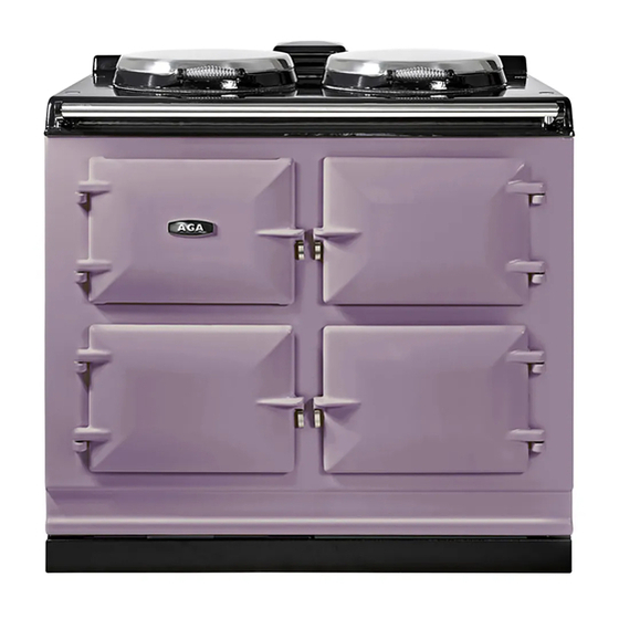
AGA AIMS EC3 Installation Instructions Manual
Electric - aims cooker
Hide thumbs
Also See for AIMS EC3:
- Owner's manual (21 pages) ,
- Users instructions & cooking manual (20 pages) ,
- Users instructions & cooking manual (13 pages)
Table of Contents
Advertisement
Quick Links
AGA ELECTRIC - AIMS
EC3 COOKER
Installation
Instructions
REMEMBER: when replacing a part on this appliance, use only spare parts that
you can be assured conform to the safety and performance specification that we
require. Do not use reconditioned or copy parts that have not been clearly
authorised by Aga.
PLEASE READ THESE INSTRUCTIONS BEFORE INSTALLING THIS APPLIANCE
For use in GB and IE
03/08 EINS 515269
Advertisement
Table of Contents

Summary of Contents for AGA AIMS EC3
- Page 1 AGA ELECTRIC - AIMS EC3 COOKER Installation Instructions REMEMBER: when replacing a part on this appliance, use only spare parts that you can be assured conform to the safety and performance specification that we require. Do not use reconditioned or copy parts that have not been clearly authorised by Aga.
-
Page 2: Table Of Contents
CONTENTS SECTION PAGE CONSUMER PROTECTION HEALTH & SAFETY INSTALLATION TECHNICAL DATA - AGA EC3 BAKING OVEN BAFFLE PLATE ELECTRICAL ELECTRICAL TEST PROCEDURE WIRING DIAGRAM TO TEST THE AIMS CONTROL HANDSET MAINS CABLE & GUIDE TUBE ASSY ELEMENTS AND ELECTRICAL HOUSING PARTS... -
Page 3: Consumer Protection
Any alteration that is not approved by Aga could invalidate the approval of the appliance, operation of the warranty and could also affect your statutory rights. In the interests of safety and effective use, please read the following before using your new Aga appliance. -
Page 4: Installation
If the Aga is to be installed in a brick recess, then the minimum clearance should be increased by at least 10mm on either side, to allow for the walls not being square and also for the natural dimensional variations found in the castings. -
Page 5: Technical Data - Aga Ec3
TECHNICAL DATA - AGA EC3 Fig. 1 DESN 514194 mm 987 889 851 679 1330 756 1125 698 484 816 116 52 55 699 662 * THIS HOLE IF REQUIRED FOR OVEN VENT PIPE IS TO BE CUT ON SITE IN THE LEFT OR RIGHT HAND SIDE PANEL. -
Page 6: Baking Oven Baffle Plate
BAKING OVEN BAFFLE PLATE A metal plate which is provided in the Aga pack MUST be positioned on the top runners of the Baking Oven. Slide the plate in fully, until it makes contact with the back of the oven. -
Page 7: Wiring Diagram
Fig. 2 TO TEST THE AIMS CONTROL HANDSET Fig. 3 Press the fan button on the handset, the vent fan symbol should show on the handset screen. The oven vent fan should operate and the fan oven neon on the control panel should illuminate. -
Page 8: Mains Cable & Guide Tube Assy
MAINS CABLE AND GUIDE TUBE ASSEMBLY Fig. 4 DESN 514243 A/ DESN 514626... -
Page 9: Elements And Electrical Housing Parts
ELEMENTS AND ELECTRICAL HOUSING PARTS ASSEMBLY Fig. 5 DESN 514245 OVEN VENT PIPE CONNECTION OPTIONS Fig. 6 DESN 514205 A... -
Page 10: Oven Thermocouple
OVEN THERMOCOUPLE NOTE: On AIMS controlled cookers the thermostat phial (probe) has been replaced by an oven thermocouple sensor, which is fitted to the PCB on the controls chassis. (See Fig. 2). 1. Feed the thermocouple sensor through the guide tube into the Roasting oven. -
Page 11: Oven Venting Systems
OVEN VENTING SYSTEMS See Figs. 9, 10, 11 & 12 Pre-site visiting will have determined where and how the layout of the oven vent pipework should be designed and installed. It is then necessary to check that the pipework design and the pipework resistance are within the parameters possible. - Page 12 Fig. 10 DESN 515278 Fig. 11 DESN 513938 Fig. 12 DESN 515431...
-
Page 13: Aims Handset
AIMS HANDSET Handset can be wall mounted as described below. Remove backplate from the rear of the Handset by sliding down with hand and away from the Handset (fig 13). Select the site for the handset and use the backplate to mark the position of fixing holes. Drill 6mm dia. -
Page 14: Instructions
Hand these instructions to the User for retention, and instruct in the safe operation of the appliance. Finally advise the User, that for continued efficient and safe operation of the appliance, it is important that adequate servicing is carried out at regular intervals recommended by the Aga Specialist. - Page 16 For further advice or information contact your local Aga Specialist With Aga’s policy of continuous product improvement, the Company reserves the right to change specifications and make modifications to the appliance described and illustrated at any time Manufactured by Station Road...


Need help?
Do you have a question about the AIMS EC3 and is the answer not in the manual?
Questions and answers