AGA eR7 100-3 User's Manual & Installation Instructions
Hide thumbs
Also See for eR7 100-3:
- Installation manual (24 pages) ,
- User's manual & installation instructions (64 pages)
Table of Contents
Advertisement
Quick Links
Model No's: eR7 100-3 and eR7 150-5
REMEMBER, when replacing a part on this appliance, use only spare parts that you can be assured conform to the safety and
DO NOT use reconditioned or copy parts that have not been clearly authorised by AGA.
AGA eR7
User Guide &
Installation Instructions
performance specification that we require.
PLEASE READ THESE INSTRUCTIONS BEFORE USING THIS APPLIANCE
PLEASE READ THESE INSTRUCTIONS BEFORE USING THIS APPLIANCE
AND KEEP IN A SAFE PLACE FOR FUTURE REFERENCE.
AND KEEP IN A SAFE PLACE FOR FUTURE REFERENCE.
For use in USA & CAN
LPRT 517928
12/21 EINS 517929
Advertisement
Table of Contents

Related Manuals for AGA eR7 100-3


Summary of Contents for AGA eR7 100-3
- Page 1 REMEMBER, when replacing a part on this appliance, use only spare parts that you can be assured conform to the safety and performance specification that we require. DO NOT use reconditioned or copy parts that have not been clearly authorised by AGA. PLEASE READ THESE INSTRUCTIONS BEFORE USING THIS APPLIANCE PLEASE READ THESE INSTRUCTIONS BEFORE USING THIS APPLIANCE AND KEEP IN A SAFE PLACE FOR FUTURE REFERENCE.
- Page 2 Make a note of your AGA eR7 Serial Number when it is being installed. The serial number can be found behind the magnetic plinth cover. My AGA Details: Serial No: AGA Service No: Date of Installation: Data badge located behind removable...
-
Page 4: Table Of Contents
14. Batteries 15. Equipment supplied with your AGA eR7 16. Fitting the Oven Shelves 17. Removing the Oven Shelves 18. Using the zones of the AGA eR7 25 The Plates The roasting oven The baking oven The simmering oven The simmering oven... -
Page 6: Product Safety
Product Safety Meaning / Description Symbol Signification / Description WARNING / CAUTION AVERTISSEMENT An appropriate safety instruction Une consigne de sécurité appropriée should be followed or caution to a doivent être suivies ou garde d’un potential hazard exists. danger potentiel exists. TENSION DANGEREUSE DANGEROUS VOLTAGE Pour indiquer les dangers... - Page 7 Important Safety Instructions INCORRECT USE OF THIS RANGE CAN INCREASE NEVER THE RISK OF FIRE, ELECTRIC SHOCKS OR INJURY Never store items of interest to TO PERSONS. children above the range. PLEASE READ THE FOLLOWING PRECAUTIONS TO Never allow children to climb on, sit REDUCE THESE RISKS.
-
Page 8: Health & Safety
• PLEASE READ THE ACCOMPANYING WARRANTY. Any • Always make sure your appliance is serviced by a alteration that is not approved by AGA could invalidate qualified technician. the approval of the appliance, operation of the warranty and could also affect your statutory rights. - Page 9 • Never cover or restrict the air flow to the controls Do not hang dish towels on the left hand side of the AGA handrail. Doing so will block the air vent. Blocking the air compartment. vent can cause excessive temperature increase to the control •...
-
Page 10: Introduction
Your new AGA eR7 gives you everything you love about the classic AGA heat storage cooker, but with the added convenience of touchscreen technology and the ability to turn each cooking area on and off, as and when you want it. -
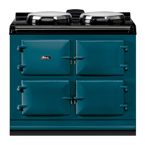
Page 11: Overview
Overview WARNING: ACCESSIBLE PARTS MAY BECOME HOT DURING USE. TO AVOID BURNS AND SCALDS CHILDREN SHOULD BE KEPT AWAY. AGA eR7 Fig. 4.1 Simmering plate Boiling plate Top plate Control door Roasting oven Baking oven Simmering oven Hotplates Baking Oven The two hotplates are at different heats;... - Page 12 WARNING: ACCESSIBLE PARTS MAY BECOME HOT DURING USE. TO AVOID BURNS AND SCALDS CHILDREN SHOULD BE KEPT AWAY. AGA eR7 with Hotcupboard Fig. 4.2 Warming plate Boiling plate Hotcupboard ON/OFF Simmering plate Slow cooking oven Top plate Warming oven Control door...
-
Page 13: How To Use Your Aga Er7
Handset Fig. 5.2 Your AGA eR7 cooker also comes with a Handset which can be used to program the ovens. It displays the time, date and program events. The hotplates work on Manual only. -
Page 14: Getting Started
Getting started Operating the hobs When switching on the AGA cooker for the first few times, Press the Hob power button which illuminates to indicate there are two things you may notice, neither of which should the hotplate and simmer buttons are ready to be activated. If cause concern. - Page 15 Operating the Ovens To override an oven setting while in slumber mode The appliance has 4 oven operating modes: No individual oven can be ‘OFF’ . However the roast or bake oven can be switched from ‘Slumber’ to a cooking setting. •...
- Page 16 AUTO/Slumber (ovens only) AUTO and AUTO/Slumber This mode setting brings selected ovens up to full heat from Changing between any of the four operating modes, will Slumber. cause the hotplates to switch OFF if in use - this is a built-in safety factor.
-
Page 17: Cooking On Your Aga Er7
Cooking on your AGA eR7 The AGA eR7 is designed to give you flexibilty when cooking a range of dishes through the four settings in the baking oven and the five settings in the roasting oven, as well as the long slow cooking in the simmering oven. -
Page 18: General Advice
When a zone has reached temperature a solid red light will indicate it has warmed up. AGA recommends that to fully saturate the castings it is best to leave them for one hour for the optimum cooking results. -
Page 19: Handset - A Hand Held Control
Handset – A hand held control Button operations Communication or ‘Handshake’ button used initially to synchronise the handset to the AGA eR7. Clock button Opens and closes the date and time settings screen. Left/Back Button Moves back and highlights the previous setting. -
Page 20: Handset Advice
Standby mode Communications fail A power cut Handset is out of range of the AGA eR7 cooker When transferring information from or to the controller always operate the handset in front of the cooker, this gives the strongest signal. -
Page 21: Communication/Handshake
Step 5 This process will be required on the original installation of the AGA eR7. If the handset is replaced for any reason the new Set the correct time and date see “The date/time setting handset will need to be synchronised. -
Page 22: The Date/Time Setting Screen
11. The date/time setting screen Press and hold Clock button until the screen is displayed. In this screen the time, date, month and year can be altered/ set. Press the buttons to alter the highlighted time, date, month and year settings. Press the buttons to cycle between the time, date, month and year. -
Page 23: Auto/Events Programme Screen
12. Auto/events programme screen This screen is opened by pressing the 7-day event button In this screen, the number of events and the start and end time of events can be set. Each day can have a different number of events, and start and end times, or all seven days can be the same. -
Page 24: Information (Home) Screen
AUTO/Slumber event OFF (during AUTO/Slumber event) Symbol indicating the battery life. If there is no communication between the AGA eR7 and the handset because: the cooker is not powered, in standby or the handset is out of range from the cooker. The symbol is displayed. -
Page 25: Batteries
The handset is fitted with four ‘AAA’ batteries, which are packed separately. Your Engineer will insert them when your AGA eR7 cooker is installed. When replacing the batteries, follow these instructions in conjunction with the diagrams. Remove the handset from its backplate, then remove the battery cover plate from the rear of the handset (Fig. -
Page 26: Equipment Supplied With Your Aga Er7
If you have not already seen a demonstration, ask your AGA Specialist for details. A demonstration will show you how to get the best from your new AGA and will give you hints and tips. You will also see a selection of AGA utensils and accessories being used. - Page 27 Toaster Wire Brush AGA Utensils and Accessories This is for toasting bread on the boiling plate. AGA toast is This is for cleaning the renowned for its excellence, crisp on the outside and soft in raw cast iron hotplate To get the very best the centre.
-
Page 28: Fitting The Oven Shelves
16. Fitting the Oven Shelves Fig. 16.1 Fig. 16.2 DESN 512403 DESN 512404... -
Page 29: Removing The Oven Shelves
17. Removing the Oven Shelves Fig. 17.1 Fig. 17.2 DESN 512405 DESN 512406... -
Page 30: Using The Zones Of The Aga Er7
AGA eR7 but is not often than not save times and washing-up! These include necessary. - Page 31 The ovens are made from cast iron, which cooks by a radiant heat and this is the secret of the cooking excellence for which the AGA cooker is renowned. An indirect radiant heat does not dry food out, so it retains its natural moisture and flavour.
-
Page 32: The Roasting Oven
The roasting oven can be used for ‘grilling’ at the top and directly onto the runners, so almost every available square ‘shallow frying’ on the oven floor, see “Cooking on your AGA centimetre of space can be used. eR7” page 12. -
Page 33: The Baking Oven
Always ensure this oven but for a longer time, see “Cooking on your AGA eR7” is in place, before putting food into the oven. -
Page 34: The Simmering Oven
This element heats the air and the cast iron within to provide cooking results consistent with the traditional simmering oven of the classic AGA heat-storage cooker, with the flexibility of being able to turn it to Off when not required. -
Page 35: Aga (Hotcupboard)
19. AGA (Hotcupboard) Slow Cooking Oven plus Warming Oven Points to remember when Slow Cooking: • Pre-heat the oven for 30 minutes before starting to These ovens are heated by a single element at the rear of the oven cavity. It is operated by a single push ON-OFF button cook. -
Page 36: Fitting And Removing The Oven Doors
CAUTION: This unit is heavy, proper equipment and adequate manpower must be used to remove the oven doors. 20. Fitting and removing the oven doors Fitting the Doors Fig. 20.1 Fig. 20.2 DESN 517491 DESN 517489 Removing the Doors Fig. 20.3 Fig. -
Page 37: Cleaning & Caring For Your Range
Top Plate and Front Plate The top of the insulated cover (lid) - this is chrome or The easiest way to clean the AGA top plate and front stainless steel and can be kept clean by wiping over with a plate is to mop up spills as they happen. - Page 38 WARNING: ACCESSIBLE PARTS MAY BECOME HOT DURING USE. TO AVOID BURNS AND SCALDS CHILDREN SHOULD BE KEPT AWAY. Roasting Pans The enamelled roasting pans supplied with the AGA eR7 should be cleaned in hot soapy water, soaking if necessary. A nylon scouring pad can also be used. They may also be cleaned in the dishwasher, but with constant use, the enamelled finish will become dull in appearance.
-
Page 39: Servicing And Warranty
The appliance warranty does not cover Commercial use (see separate Warranty book provided for further details). Error codes In the unlikely event an error occurs with your AGA eR7 cooker, error codes may be displayed on your handset, for example: 3.11... -
Page 40: Installation Instructions
REMEMBER, when replacing a part on this appliance, use only spare parts that you can be assured conform to the safety and performance specification that we require. DO NOT use reconditioned or copy parts that have not been clearly authorised by AGA. PLEASE READ THESE INSTRUCTIONS BEFORE USING THIS APPLIANCE... -
Page 41: Installation Requirements
(1005mm) x 29 1/8” (740mm) could be used to check if the adequate and in conformance with the regulations. AGA eR7 fully built appliance is able to fit through the Take special care when cutting holes in walls or floor. -
Page 42: Location
Surfaces over the top of the range must not be closer than If the AGA is to be installed in a brick recess, then the 30” (760 mm). minimum clearance should be increased by at least ”... -
Page 43: Clearances
26. Clearances Fig. 26.1 DESN 516298... - Page 44 Make sure that the plinth facia is centrally located and does not overhang the range. Commission the AGA eR7, as stated in the relevant Installation Instructions and carry out functional test on each of the features of the AGA eR7.
-
Page 45: Appliance Dimensions
3/8” beyond the figures quoted above. This allows safe margin to take into account the natural dimensional variations found in major castings. In particular the width across the appliance recess could be critical. APPLIANCE WEIGHT Model: AGA eR7 - 816 lb... - Page 46 3/8” beyond the figures quoted above. This allows safe margin to take into account the natural dimensional variations found in major castings. In particular the width across the appliance recess could be critical. APPLIANCE WEIGHT Model: AGA eR7 - 816 lb Hotcupboard - 243 lb...
-
Page 47: Connection To The Power Supply
28. Connection to the Power Supply Electric Shock Hazard The rating plate is located behind the removable plinth, see Fig. 28.2. If the supply cord is damaged, it must be replaced by the manufacturer, its service agent or similarly qualified person to avoid a hazard. Electrical Grounding is required on this appliance. - Page 48 Mains Supply Location Fig. 28.1 Mains cable fed from control tray right-hand exit through ducting dependent upon position of supply socket DESN 517444 Fig. 28.2 Data plate located behind toe-kick, pull toe-kick to remove. The mains supply connection and isolation point must be within the zone shown DESN 516295...
-
Page 49: Aga Hotcupboard Connections
SIMILARLY QUALIFIED PERSON TO AVOID A HAZARD. A 120v ~ 60 Hz, 5 amp fused electrical supply is required adjacent to the appliance (with the exception of the AGA Hotcupboard with Induction Hob model, please refer to the AGA Induction Hob model instructions for the power supply requirements). -
Page 50: Mains Supply Location
29. Mains Supply Location Mains cable routing Fig. 29.1 Mains cable fed from control tray right- hand exit through ducting dependent upon position of supply socket DESN 517783 Fig. 29.2 THE MAINS SUPPLY CONNECT POINT MUST BE WITHIN THE ZONES SHOWN DESN 517784... -
Page 51: Mains Cable Routing- Aga Hotcupboard
Mains cable routing- AGA Hotcupboard Fig. 29.3 HOTCUPBOARD POWER SUPPLY Mains cable fed from control tray right- hand exit through ducting dependent upon position of supply socket DESN 517785 Fig. 29.4 THE MAINS SUPPLY CONNECT POINT MUST BE WITHIN THE ZONES SHOWN... -
Page 52: Hotcupboard Installation
30. Hotcupboard installation NOTE: The AGA hotcupboard should arrive with the top plate in a jacked up position (except for induction top versions which will arrive with the top fully wound down). This is to allow the complete appliance to be slid onto its plinth when alongside the AGA eR7 without the top plates clashing. - Page 53 Check with a spirit level that the plinth level is correct, and also check height differential between the hotcupboard plinth and AGA eR7 plinth is correct 7/16 “ (11 mm). If necessary, use shims in each corner to level the plinth.
- Page 54 Run a straight edge along the front of the AGA eR7 plinth, to ensure the front face of both plinths sit squarely against the straight edge. (Fig. 30.5) USE STRAIGHT EDGE ACROSS BOTH PLINTHS TO ENSURE PLINTHS ARE ALIGNED SQUARELY Fig.
- Page 55 DESN 516552 The hotcupboard top plate is set 3/16 “ (5mm) higher than the AGA eR7 top plate. This is to prevent damage to the enamel during installation. Lower the top plate using the adjusters (Fig. 30.8 and Fig. 30.9).
- Page 56 AGA eR7. (Fig. 30.9). For servicing requirement, top plate should be removed by raising adjusters approximately 3/16 “ (5mm), the top plate can now be removed easily without causing damage to the enamelled surfaces.
- Page 57 10. Next the handrail, endcaps and handrail require assembly. Slide the handrail through the handrail brackets. AGA eR7 HANDRAIL CONNECTION Fig. 30.11 DESN 516880 11. On 5 oven appliances, fit ‘allthread’ stud into the threaded end of the handrail, then feed the handrail...
- Page 58 5 oven appliances the right hand side of the module plinth facia sits against the left hand side of the AGA eR7 plinth facia leaving no gap between. Make sure that the plinth facias are centrally located and do not overhang either appliance.
-
Page 59: Circuit Diagram
31. Circuit Diagram AGA Hotcupboard Caution: label all wires prior to disconnection, when servicing controls wiring errors can cause improper and dangerous operation. Verify proper operation after servicing DESN 517488 Code Colour Blue Brown Black Orange Green... - Page 60 AGA eR7 MAINS IN EARTH CABLE C/W RING TONGUES WHITE Park BLACK EARTH GREEN CONTROLS TRAY EARTH EARTH CABLE SLEEVED, C/W RING TONGUES BOILING / SIMMERING PLATE EARTH G/Y or G ROAST OVEN BACKPLATE MAIN CONTROL BOARD Fig. 31.1...
- Page 64 For further advice or information contact your local AGA Specialist With AGA Marvel’s policy of continuous product improvement, the Company reserves the right to change specifications and make modifications to the appliance described and illustrated at any time. Middleby Residential...
Need help?
Do you have a question about the eR7 100-3 and is the answer not in the manual?
Questions and answers