Table of Contents
Advertisement
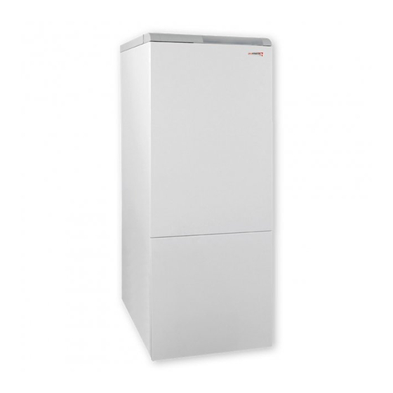
Bear
Operation and
Installation Guide
20, 30, 40, 50 KLZ
Stationary cast iron boiler
Output range 17 – 44.5 kW
Continuous output modulation
Integrated 110 l hot water tank
www.protherm.eu
EN
Protherm spol. s r.o.
Your service organisation:
Pplk. Pľjušťa 45
v e r s i o n
909 01 Skalica, Slovakia
Tel.: +421 34 6966 101
Fax: +421 34 6966 111
xxxx_01 - v.3 2/2007
Advertisement
Table of Contents

Related Manuals for Protherm Bear 20 KLZ


Summary of Contents for Protherm Bear 20 KLZ
-
Page 1: Installation Guide
Stationary cast iron boiler Output range 17 – 44.5 kW Continuous output modulation Integrated 110 l hot water tank www.protherm.eu Protherm spol. s r.o. Your service organisation: Pplk. Pľjušťa 45 v e r s i o n 909 01 Skalica, Slovakia Tel.: +421 34 6966 101... -
Page 2: Table Of Contents
Bear 20 (30, 40, 50) KLZ The boiler’s Serial no. is shown on the plate which is attached to the rear side of the control panel. The control panel is accessible after removing the front cover. In the section “Operating Instructions” you will fi nd description of the boiler’s main functions and guidelines on how to handle the boiler safely. -
Page 3: Introduction
Introduction 1. The boiler and all the associated operation. equipment must be installed and used in 9. Whenever you are not suffi ciently certain accordance with the installation design, of how to control the boiler, seek out and corresponding valid legal study all the corresponding instructions prescriptions and technical norms and... - Page 4 the Operation guide, Service Book etc.). for type C gas appliances, i.e. in closed “TURBO” version If the boiler is not put into operation, the • In addition to the above mentioned original packaging of the boiler must be documents, it is necessary when using available potential further...
-
Page 5: Operating Instructions Controls And Signals
Operating instructions Operating instructions Controls and signals Fig. 1 Main switch The control panel has the following control elements (Fig.1): The main switch (Fig. 1, Position 7) is 1 Timer switch – sets attenuation of tank used to switch the boiler on or off. The heating and attenuation of heating water. -
Page 6: Selecting Read Mode
Selecting Read mode Displaying heating water Note: Switch between the display of the current temperature of the heating water temperature and the temperature of the hot water in After turning the tank using the button. boiler on by pressing the main switch, the Other values on display current temperature water... - Page 7 Equithermal mode Curve slope Setting equithermal mode, i.e. selection of the equithermal curve slope and parallel shift of the curve, is possible only in the case that an outdoor sensor is attached to the boiler. Note: If no outdoor sensor is attached, the boiler will not enable the user to transfer to setting mode E and P.
-
Page 8: Schematic Diagram Of Boiler Control
Schematic diagram of boiler control Fig. 4... -
Page 9: Error Codes
Timer switch The timer switch serves for setting attenuation of heating the hot water in the tank, i.e. during the interval of the set attenuation the boiler does not heat the water in the hot water tank to maintain temperature. The length of the attenuation interval is set by the cogs on the perimeter of the clock rotor. -
Page 10: Starting Up And Shutting Down Boiler
Note: Use control units recommended and Using the boiler with a room control supplied by the PROTHERM company, unit which are designated and tested for the given type of boiler. In the case of use of... -
Page 11: Protection Functions
Operation of boiler with equithermal tank, the boiler automatically switches to the mode of heating the hot water in control the tank. After heating the hot water to The boiler regulates the heating water the required temperature the boiler is temperature on the basis of outdoor automatically switched to the regime of temperature changes. -
Page 12: Service And Maintenance
than 85°C. The boiler is switched off when unblock the boiler using the RESET the temperature of the heating water is button. higher than 90°C (fault F3). Note: The boiler may be blocked as a consequence of overheating caused by Running pump depending on the pump being switched off as a result of heating water temperature... -
Page 13: Warranty And Warranty Conditions
Warranty and warranty conditions The PROTHERM Bear 20 (30, 40, 50) KLZ is covered by the warranty defi ned in the Warranty Certifi cate, the Service Book and by other conditions specifi... -
Page 14: Technical Specifi Cations
Technical specifications 20 (30) KLZ Bear 20 KLZ Bear 30 KLZ Category ..........II 2H3P Version . - Page 15 Technical specifications 40 (50) KLZ Bear 40 KLZ Bear 50 KLZ Category ..........II 2H3P Version .
-
Page 16: Connection Dimensions
Connection dimensions of boiler 20 (30, 40, 50)KLZ TYPE ød 20 KLZ 327,5 177,5 30 KLZ 40 KLZ 242,5 262,5 50 KLZ A – hot water input 3/4” B – hot water circulation 3/4” C – hot water output 3/4” D –... -
Page 17: Schematic Diagram Of Boiler
Schematic diagram of boiler 1. Control panel 10. Backfl ow valve for HeW circuit 19. Hot water (cold water) inlet 2. “POLO-TURBO” superstructure 11. Backfl ow valve for HoW circuit 20. Filling and discharge 3. Combustion gas collector 12. Gas inlet 21. -
Page 18: Installation Instructions
Installation instructions Installation instructions Introduction The PROTHERM Bear 20 (30, 40, 50) In the case of clogging of the system with KLZ boiler is compatible with common dirt from the heating system or incrusta- types of hot water heating systems and tion sediments or problems caused by heating radiators. - Page 19 Pa. The boiler is connected to the chimney metre of even section or 1 90° joint). inlet by a fl ue – for the boilers PROTHERM Mounting the superstructure onto the 20, 30 KLZ with Ø 130 mm, for the type boiler and putting into operation may PROTHERM 40 KLZ with Ø...
- Page 20 stress on all its elements during operation. has a combined calcium and magnesium In cases where the total quantity of heating concentration greater than 1.8 mmol/l, it is water in the closed system exceeds 180 l it useful to implement other “non-chemical” is essential to include a second expansion measures against incrustation (e.g.
-
Page 21: Delivery Completeness
Delivery completeness Content of boiler delivery Content of delivery PROTHERM Bear 20 (30, 40, 50) KLZ boilers are supplied completely assembled functionally tested. Associated armatures (safety valve and backfl ow clack valve) are enclosed with the boiler for equipment for the hot water inlet, as well as a set of adjustable legs. -
Page 22: Preparing For Boiler Installation
Boiler equipment of the system (i.e. of the boiler and heating system together); the outlet from this is The boiler PROTHERM 20 (30, 40, 50) the section of the gas piping of the burner KLZ comprises the following parts: plate fi nished with 2 to 4 jets (one on each - cast iron boiler body with thermal burner pipe). - Page 23 Casing Placing of boiler This is composed of covers, fi rmly The boiler is fi tted on a construction base, attached to the back wall and side plates, i.e. a platform (or pedestal). The platform a detachable frontal wall and detachable must have at least a regular load capacity upper part.
-
Page 24: Installing The Boiler
Installing the boiler In the case of service interventions into direction of the utility water) it is desirable the boiler it is unconditionally necessary to install also a stopper, which is not whenever the boiler is collected to the included in the boiler delivery. electrical power source (even when the The combined armature is always installed mains switch of the boiler is off) to abide by... - Page 25 damage, and must be replaced with will be practically unchanged. So when new ones before the end of their useful “throw” takes place during relaxation of life or before their reliability to meet their the pressure from the equalizing gas part nominal parameters (as stated by their and the pressure watershed of the sought manufacturers) is diminished.
-
Page 26: Operating The Boiler
Operating the boiler Preparing and starting the boiler forming solution. It is necessary to rectify any determined leakages and repeat the Check the water pressure on the boiler check. pressure gauge. By opening the gas cock At the end of preparing and starting the gas is inlet into the boiler. - Page 27 First heating Before commencing setting, when the boiler is switched off (plug of electrical The fi rst heating is a short, sharp operation power cord is removed from socket), it is of the boiler after its initial connection to necessary to: the heating system.
-
Page 28: Service Modes
Service (additional) modes Setting attenuation in heating button and subsequently confi rmed with the MODE button, which at the same The parameter “u” time transfers the boiler into the next appears mode. display and the diode fl ashes in the upper Values of “t”... -
Page 29: Electrical Connection Of Boiler
Electrical connection of boiler The boiler is connected to power supply The terminal for connection of the room by a three-core fl exible cord with a plug. control units is equipped from the factory A fi xed socket through which the boiler is with a jumper and is located in the electrical connected to power mains must comply box of the boiler. -
Page 30: Converting To Different Fuel
Diagram of connection of external elements Terminals for connecting outdoor sensor Room control unit Select this connection only if BOILER you want to connect Power cable a room control unit Connection of external control unit (without plug) (not part of delivery) Main power connection (230V) Fig. - Page 31 – otherwise this could cause damage only original parts supplied by the (tearing) of “SOFT-LITE”). The red rotating manufacturer or person authorised by the knob underneath the plug has an arrow, manufacturer are used. Reconstruction which: may be performed only by a qualifi ed technician! In changing the type of fuel it - if turned in the direction of gas fl...
Need help?
Do you have a question about the Bear 20 KLZ and is the answer not in the manual?
Questions and answers