Advertisement
Table of Contents
Advertisement
Table of Contents

Summary of Contents for Protherm 65
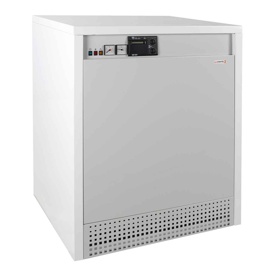
- Page 1 Grizzly Manual for instruction and use of boiler 65, 85, 100, 130, 150 KLO Floorstanding cast iron boiler Cascade conection possible Output up to 150 kW www.protherm.sk Protherm spol. s r.o. v e r z i o n Jurkovičova 45 909 01 Skalica Tel.: 034 6966 101...
-
Page 2: Regulations And Directives
Part 7: Requirements on these Operating Instructions, the connected equipment!). special installations or premises. Section The PROTHERM KLO boiler may be – abide by applicable regulations and 5. The service technician when putting 701. Rooms with a bath-tub…... -
Page 3: Boiler Features
Government De- d ) Chimney: Setting this value above usual tempera- b) 65, 85, 100, 130, 150 KLO EKO crees Nos. 392/99, 393/99 and 393/99 as ture (50-60°C) will result in longer heating STN 73 4210 – Construction of chimneys The boilers use as fuel natural gas and set forth in Act No. - Page 4 18000 16000 130 KLO / KLO EKO 14000 100 KLO / KLO EKO 12000 10000 65, 85 KLO / KLO EKO 8000 6000 4000 2000 Flow of water volume V (m 3 /h) objemový prùtok vody V (m /h) Fig. 2...
- Page 5 The PROTHERM Series 65 – 85 KLO - P / Connecting the boiler to gas supply 65 - 85 KLO EKO - P boilers are designed to run on propane gas.
- Page 6 (all in accordance with range on the heating controls. This setting The PROTHERM KLO / KLO EKO boilers Ministry of Environment Public Notice No. must be done by authorised service only. are designed for heating water of up to 706/2002).
- Page 7 Before final installation of the boiler, the The boiler must be placed on a building Prevention against freezing The boiler has an outlet for connecting heating system distribution pipes must be base, i.e. floor (or on a pedestal). The a room thermostat, located on a printed Unless the boiler is protected against flushed several times by pressurised wa- floor must have at least normal load-bear-...
-
Page 8: Description Of Control Elements
Max. power / Low power (kW) Max. power (kW) PROPAN 11. Emergency thermostat NATURAL GAS 12. Combustion gases thermostat Fig. 5 65 / 49 55 / - 13. RESET button 85 / 59 14. Power mains fuse (4 A) 99 / 70... -
Page 9: Important Guidelines
LOM. thrust, blocked chimney), the reverse power mains switch on the boiler’s control nance and repairs done by a PROTHERM fumes flow cutout device will shut off the In addition to the measures taken in prac- panel. -
Page 10: Boiler Shutdown
er applicable regulations. Incorrect use of – when the heating system water tempe- Maintenance the boiler might result in reducing its life, rature in the boiler reaches the values but also in damages to health and prop- set on the operating heating water ther- We recommend that once a year, prefer- is wet, wait until it dries before reconnect- erty. -
Page 11: Transportation And Storage
Boiler type ....65 KLO ..85 KLO ..100 KLO .. -
Page 12: Installing The Boiler
Boiler type ....65 KLO EKO . . .85 KLO EKO 100 KLO EKO 130 KLO EKO 150 KLO EKO Installing the Boiler Number of elements . -
Page 13: Electrical Wiring
The top cover can be removed after the The operating control unit limiting is done Electrical wiring two self-cutting screws located at the back with an arresting wire clip situated inside The boiler’s electrical compartment as and the boiler thermostat using an RVA of the boiler have been removed. - Page 14 ching kit of the equithermal control unit. Important: The pump thermostat will – The boiler may be restarted only after Check the connector and make sure remain unused. The heating system pro- the sensor of the reverse fumes flow sa- that it has not interconnected for instan- tection function must be provided by the fety device has cooled off, i.e.
-
Page 15: Operation
(see Fig. 29). If repeated attempts to 4. Remove the jets from the burner con- button models 65 and 85 KLO / KLO EKO. The ignite the burner fail, the main switch must 100 °C 50 °C... -
Page 16: Gas Pressure Settings
Gas pressure settings er and turn it by 180°. When running the nal manufacturer-supplied or authorised 65 - 100 KLO / KLO EKO Standard – 10. Check the pressure gauge (U-tube) boiler on propane gas, the arrow must be parts. When converting to a different type reading. - Page 17 Table 5: Pressure of gas settings for KLO EKO – natural gas / propane 8. Remove the aluminium plug on gas valve 1 and lightly turn the plastic output Model 65 KLO EKO 85 KLO EKO 100 KLO EKO 130 KLO EKO 150 KLO EKO adjusting screw found inside.
- Page 19 Legend to schematic electric diagrams for the 65 - 150 KLO / KLO EKO boilers - main switch - power mains fuse PT-TOP - heating operation controls - fault reset button, RESET - red glow tube - fault indication control...


Need help?
Do you have a question about the 65 and is the answer not in the manual?
Questions and answers