Table of Contents
Advertisement
Quick Links
Advertisement
Chapters
Table of Contents

Related Manuals for IEI Technology IBM-Q354


Summary of Contents for IEI Technology IBM-Q354
- Page 1 IMB-Q354 uATX Motherboard IMB-Q354 uATX Motherboard Page i...
- Page 2 IMB-Q354 uATX Motherboard Revision Date Version Changes 2008-01 1.00 Initial release Page ii...
- Page 3 IMB-Q354 uATX Motherboard Manual Conventions WARNING! Warnings appear where overlooked details may cause damage to the equipment or result in personal injury. Warnings should be taken seriously. Warnings are easy to recognize. The word “warning” is written as “WARNING,” both capitalized and bold and is followed by text.
- Page 4 IMB-Q354 uATX Motherboard CAUTION: This is an example of a caution message. Failure to adhere to cautions messages may result in permanent damage to the IMB-Q354. Please take caution messages seriously. NOTE: These messages inform the reader of essential but non-critical information. These messages should be read carefully as any directions or instructions contained therein can help avoid making mistakes.
- Page 5 IMB-Q354 uATX Motherboard Copyright COPYRIGHT NOTICE The information in this document is subject to change without prior notice in order to improve reliability, design and function and does not represent a commitment on the part of the manufacturer. In no event will the manufacturer be liable for direct, indirect, special, incidental, or consequential damages arising out of the use or inability to use the product or documentation, even if advised of the possibility of such damages.
-
Page 6: Packing List
NOTE: If any of the components listed in the checklist below are missing, please do not proceed with the installation. Contact the IEI reseller or vendor you purchased the IMB-Q354 from or contact an IEI sales representative directly. To contact an IEI sales representative, please send an email to sales@iei.com.tw. -
Page 7: Table Of Contents
IMB-Q354 uATX Motherboard Table of Contents INTRODUCTION..................... 1 1.1 O ......................... 2 VERVIEW 1.1.1 IMB-Q354 Features ................... 3 1.2 IMB-Q354 O ....................3 VERVIEW 1.2.1 IMB-Q354 Overview Photo ................3 1.2.2 IMB-Q354 Peripheral Connectors and Jumpers..........4 1.2.3 Technical Specifications..................6 DETAILED SPECIFICATIONS ................ - Page 8 IMB-Q354 uATX Motherboard ® 2.5.4 Intel ICH9DO Ethernet Controller ..............21 2.5.4.1 Intel® 82566DM Gigabit LAN Connect Device........22 ® 2.5.5 Intel ICH9DO Low Pin Count (LPC) Interface..........23 ® 2.5.6 Intel ICH9DO PCI Interface................24 ® 2.5.7 Intel ICH9DO PCIe x4 Bus................24 ®...
- Page 9 IMB-Q354 uATX Motherboard 2.10 E ............. 38 NVIRONMENTAL AND OWER PECIFICATIONS 2.10.1 System Monitoring ..................38 2.10.2 Operating Temperature and Temperature Control......... 38 2.10.3 Power Consumption..................39 UNPACKING ......................41 3.1 A ..................42 STATIC RECAUTIONS 3.2 U ......................42 NPACKING 3.2.1 Unpacking Precautions..................
- Page 10 IMB-Q354 uATX Motherboard 4.3 E ......... 69 XTERNAL ERIPHERAL NTERFACE ONNECTOR ANEL 4.3.1 Audio Connectors..................... 69 4.3.2 Keyboard/Mouse Connector ................70 4.3.3 LAN and Dual USB Combo Connectors............71 4.3.4 Parallel Port, Serial Port and VGA Combo Connector........73 INSTALLATION ....................77 5.1 A ..................
- Page 11 IMB-Q354 uATX Motherboard 5.8.2 LAN Connection (Single Connector) ............. 102 5.8.3 Parallel Device Connection................103 5.8.4 PS/2 Keyboard and Mouse Connection ............104 5.8.5 Serial Device Connection ................105 5.8.6 USB Device Connection................. 106 5.8.7 VGA Monitor Connection ................107 AMI BIOS......................
- Page 12 IMB-Q354 uATX Motherboard 6.5.3 Hard Disk Drives ................... 149 6.6 S ....................... 150 ECURITY 6.7 C ......................... 151 HIPSET 6.7.1 NorthBridge Configuration................152 6.7.2 Southbridge Configuration ................154 6.8 E ........................156 SOFTWARE DRIVERS ..................159 7.1 A ................160 VAILABLE OFTWARE RIVERS...
- Page 13 IMB-Q354 uATX Motherboard ADDRESS MAPPING ..................233 E.1 A ..................... 234 DDRESS E.2 1 MB M ............... 234 EMORY DDRESS E.3 IRQ M ................... 235 APPING ABLE E.4 DMA C ................235 HANNEL SSIGNMENTS COMPATIBILITY....................237 F.1 C ................ 238 OMPATIBLE PERATING YSTEMS...
- Page 14 IMB-Q354 uATX Motherboard List of Figures Figure 1-1: IMB-Q354 uATX Motherboard ...................2 Figure 1-2: IMB-Q354 Overview [Front View]................4 Figure 2-1: IMB-Q354 Dimensions (mm) ...................10 Figure 2-2: External Interface Panel Dimensions (mm)............11 Figure 2-3: Data Flow Block Diagram..................12 Figure 2-4: Front Side Bus (FSB) ....................16 Figure 2-5: DDR2 DIMM Sockets ....................16 Figure 2-6: VGA Connector ......................18 Figure 2-7: DMI Chip-to-Chip Connection.................19...
- Page 15 Figure 5-2: Remove the CPU Socket Protective Shield............83 Figure 5-3: Open the CPU Socket Load Plate................84 Figure 5-4: Insert the Socket LGA775 CPU................85 Figure 5-5: IEI CF-520 Cooling Kit .....................86 Figure 5-6: Securing the Heat sink to the PCB Board .............87 Figure 5-7: DDR2 Channels ......................88 Figure 5-8: Installing a DIMM......................90...
- Page 16 IMB-Q354 uATX Motherboard Figure 5-17: Audio Connectors ....................102 Figure 5-18: LAN Connection ....................103 Figure 5-19: Parallel Device Connector.................. 104 Figure 5-20: PS/2 Keyboard/Mouse Connector ..............105 Figure 5-21: Serial Device Connector..................106 Figure 5-22: USB Device Connection ..................107 Figure 5-23: VGA Connector ....................
- Page 17 IMB-Q354 uATX Motherboard Figure 7-26: Intel® 82566DM Driver Setup Options .............. 177 Figure 7-27: Intel® 82566DM Driver Installation Ready Window ......... 177 Figure 7-28: Intel® 82566DM Driver Installation Progress ........... 178 Figure 7-29: Intel® 82573 Driver Directory Icon ..............179 Figure 7-30: Intel®...
- Page 18 IMB-Q354 uATX Motherboard Figure 7-58: Matrix Storage Manager License Agreement........... 197 Figure 7-59: Matrix Storage Manager Readme File ............... 198 Figure 7-60: Matrix Storage Manager Setup Complete............198 Figure 7-61: IAMT Driver Directory ..................199 Figure 7-62: IAMT Driver Installation Icon ................200 Figure 7-63: IAMT Welcome Screen ..................
- Page 19 IMB-Q354 uATX Motherboard List of Tables Table 1-1: Technical Specifications.....................7 Table 2-1: Supported Intel® Core™2 Duo (Conroe) Processors ..........15 Table 2-2: Supported Intel® Celeron® Processors..............15 Table 2-3: Power Consumption....................39 Table 3-1: Package List Contents ....................44 Table 3-2: Package List Contents ....................45 Table 4-1: Peripheral Interface Connectors ................50 Table 4-2: Rear Panel Connectors .....................51 Table 4-3: ATX Power Connector Pinouts ................52...
- Page 20 Table 5-2: Clear CMOS Jumper Settings...................92 Table 5-3: COM Port Pin 9 Setting Jumper Settings..............93 Table 5-4: COM Port Pin 9 Voltage Setting Jumper Settings..........94 Table 5-5: IEI Provided Cables ....................96 Table 6-1: BIOS Navigation Keys .................... 111 Page xx...
- Page 21 IMB-Q354 uATX Motherboard BIOS Menus Menu 1: Main ..........................112 Menu 2: Advanced........................114 Menu 3: CPU Configuration..................... 115 Menu 4: IDE Configuration ...................... 116 Menu 5: IDE Master and IDE Slave Configuration..............118 Menu 6: IDE Master and IDE Slave Configuration..............123 Menu 7: Super IO Configuration .....................
-
Page 22: This Page Is Intentionally Left Blank
IMB-Q354 uATX Motherboard THIS PAGE IS INTENTIONALLY LEFT BLANK Page xxii... -
Page 23: Introduction
IMB-Q354 uATX Motherboard Chapter Introduction Page 1... -
Page 24: Overview
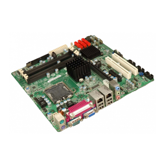
IMB-Q354 uATX Motherboard 1.1 Overview Figure 1-1: IMB-Q354 uATX Motherboard The IMB-Q354 uATX form factor motherboard (Figure 1-1) is an LGA775 Intel® Core™2 Quad, Intel® Core™2 Duo or Intel® Celeron® CPU processor platform. Both 45nm core (Wolfdale, Yorkfield) and 65nm core (Conroe) processors are supported. (For a full list of supported processors please refer to Section 2.3) Up to four 2.0 GB 667 MHz or 800 MHz un-buffered DDR2 SDRAM DIMM are supported by the Intel®... -
Page 25: Imb-Q354 Features
IMB-Q354 uATX Motherboard 1.1.1 IMB-Q354 Features Some of the IMB-Q354 features are listed below. Supports the following Intel® LGA775 processors: Intel® Core™2 Duo (45nm and 65nm) Intel® Core™2 Quad (45nm and 65nm) Intel® Celeron® (65nm) Supports four 240-pin 2 GB 667 MHz or 800 MHz DDR2 DIMMs Six SATA II drives with transfer rates of 3.0 Gbps supported Twelve USB 2.0 devices supported (eight onboard and four on the rear panel) Dual GbE Ethernet connectors... -
Page 26: Imb-Q354 Peripheral Connectors And Jumpers
IMB-Q354 uATX Motherboard Figure 1-2: IMB-Q354 Overview [Front View] 1.2.2 IMB-Q354 Peripheral Connectors and Jumpers The IMB-Q354 has the following connectors on-board: 1 x ATX power connector 1 x Audio connector 1 x CD in connector 1 x Cooling fan connector, CPU Page 4... - Page 27 IMB-Q354 uATX Motherboard 1 x Cooling fan connector, System 1 x CPU power connector 1 x Digital input/output connector 4 x DIMM sockets 1 x Floppy drive connector 1 x Front panel connector 1 x Infrared (IrDA) connector 2 x PCI slots 1 x PCIe x16 slots 1 x PCIe x4 slots 1 x PCIe power connector...
-
Page 28: Technical Specifications
IMB-Q354 uATX Motherboard 1.2.3 Technical Specifications IMB-Q354 technical specifications are listed in Table 1-1. See Chapter 2 for details. Specification IMB-Q354 Form Factor uATX LGA775 Intel® Core™2 Quad System CPU LGA775 Intel® Core™2 Duo LGA775 Intel® Celeron® Front Side Bus (FSB) 800 MHz, 1066 MHz or 1333 MHz Northbridge: Intel®... -
Page 29: Table 1-1: Technical Specifications
IMB-Q354 uATX Motherboard Four by external connectors SATA Six 3.0 Gb/s SATA II drives supported RAID 0, RAID 1, RAID 5 and RAID 10 SATA RAID Levels Keyboard/mouse By external PS/2 connector through the ITE IT8712F super I/O One 8-bit digital input/output connector; 4-bit input/4-bit output Digital I/O through the ITE IT8712F super I/O Software programmable 1-255 sec. - Page 30 IMB-Q354 uATX Motherboard THIS PAGE IS INTENTIONALLY LEFT BLANK Page 8...
-
Page 31: Detailed Specifications
IMB-Q354 uATX Motherboard Chapter Detailed Specifications Page 9... -
Page 32: Dimensions
IMB-Q354 uATX Motherboard 2.1 Dimensions 2.1.1 Board Dimensions The dimensions of the board are listed below: Length: 243.84mm Width: 243.84mm Figure 2-1: IMB-Q354 Dimensions (mm) Page 10... -
Page 33: External Interface Panel Dimensions
IMB-Q354 uATX Motherboard 2.1.2 External Interface Panel Dimensions External peripheral interface connector panel dimensions are shown in Figure 2-2. Figure 2-2: External Interface Panel Dimensions (mm) Page 11... -
Page 34: Data Flow
IMB-Q354 uATX Motherboard 2.2 Data Flow Figure 2-3 shows the data flow between the two on-board chipsets and other components installed on the motherboard and described in the following sections of this chapter. Figure 2-3: Data Flow Block Diagram Page 12... -
Page 35: Compatible Processors
IMB-Q354 uATX Motherboard 2.3 Compatible Processors 2.3.1 Supported Processors Overview The IMB-Q354 supports the following Intel® LGA775 processors Intel® Core™2 Quad (Yorkfield) Intel® Core™2 Duo (Wolfdale) Intel® Core™2 Duo (Conroe) Intel® Celeron® (Conroe) 2.3.2 Supported Intel® Core™2 Quad (Yorkfield) Processors The Yorkfield core Intel®... -
Page 36: Supported Intel® Core™2 Duo (Wolfdale) Processors
IMB-Q354 uATX Motherboard 2.3.3 Supported Intel® Core™2 Duo (Wolfdale) Processors The Wolfdale core Intel® Core™2 Duo CPU is a 45nm LGA775 processor. NOTE: As of the date of writing this manual (December, 2007), Intel® has not released Wolfdale core Intel® Core™2 Duo processor numbers that are supported by the Intel®... -
Page 37: Supported Intel® Celeron® (Conroe) Processors
IMB-Q354 uATX Motherboard Processor # CPU Speed FSB Speed Cache Size E6850 3.0 GHz 1333 MHz 4 MB Table 2-1: Supported Intel® Core™2 Duo (Conroe) Processors 2.3.5 Supported Intel® Celeron® (Conroe) Processors Table 2-1 lists the Conroe core Intel® Celeron® processors supported on the IMB-Q354. All the processors in Table 2-1 are 65nm LGA775 processors with the following features: Execute Disable Bit Intel®... -
Page 38: Intel® Q35 Memory Controller
IMB-Q354 uATX Motherboard 1333 MHz The LGA775 socket, Intel® Q35 Northbridge and the FSB are shown in Figure 2-4. Figure 2-4: Front Side Bus (FSB) 2.4.3 Intel® Q35 Memory Controller The memory controller on the Intel® Q35 Northbridge can support up to 8.0 GB of DDR2 SDRAM. -
Page 39: Intel® Q35 Pcie X16 Interface
IMB-Q354 uATX Motherboard CAUTION: If more than one DDR2 DIMM is being installed in the system, please purchase two DIMM that have the same capacity and operating frequency. Each DIMM socket can support DIMMs with the following specifications: DDR2 only Un-buffered only 667 MHz or 800 MHz 2.0 GB maximum capacity per DIMM (8.0 GB supported with four DIMM) -
Page 40: Intel® Q35 Graphics And Display Features
IMB-Q354 uATX Motherboard 2.4.5 Intel® Q35 Graphics and Display Features NOTE: The Intel® Q35 Graphics and Display Features can be configured in the Northbridge BIOS configuration screen. Please refer to Section 6.7.1 on page 152. The Intel® Q35 GMCH integrated graphics device (IGD) has 3D, 2D and video capabilities. The Unified Memory Architecture (UMA) uses up to 256 MB of Dynamic Video Memory Technology (DVMT) for graphics memory. -
Page 41: Intel® Q35 Direct Media Interface (Dmi)
IMB-Q354 uATX Motherboard Some of the capabilities of the Intel® Q35 analog CRT port are listed below: 400 MHz Integrated 24-bit RAMDAC Up to 2048x1536 @ 75 Hz refresh Hardware Color Cursor Support DDC2B Compliant Interface 2.4.7 Intel® Q35 Direct Media Interface (DMI) The Direct Media Interface (DMI) is the communication bus between the Intel®... -
Page 42: Intel ® Ich9Do Southbridge Chipset
IMB-Q354 uATX Motherboard ® 2.5 Intel ICH9DO Southbridge Chipset ® 2.5.1 Intel ICH9DO Overview Intel® ICH9DO Southbridge is an advanced I/O controller hub (ICH) connected to the Intel® Q35 Northbridge through a DMI connection. The Intel® ICH9DO has six PCIe x1 ports, supports up to twelve USB 2.0 devices, six 3.0 Gbps SATA II drives with Intel®... -
Page 43: Intel® Ich9Do High Definition Audio Implementation
IMB-Q354 uATX Motherboard 2.5.3 Intel® ICH9DO High Definition Audio Implementation A RealTek ALC883 High Definition Audio (HDA) codec is interfaced through the Intel® High Definition Audio serial link to the HDA controller integrated on the Intel® ICH9DO. The audio connector is shown in Figure 2-8. Figure 2-8: Audio Connectors ®... -
Page 44: Intel® 82566Dm Gigabit Lan Connect Device
IMB-Q354 uATX Motherboard NOTE: To enable the Intel® ICH9DO GbE Wake-on LAN function, the Wake-on LAN function must be enabled in the BIOS. Please refer to Section 6.5.1 (the Boot Settings Configuration menu) on page 146. Some of the features of the Intel® ICH9DO GbE controller are listed below. Supports multi speeds including 10 Mbps, 100 Mbps and 1000 Mbps Can operate in full-duplex mode at all supported speeds Can operate at half-duplex at 10 MBps and 100 MBps... -
Page 45: Intel ® Ich9Do Low Pin Count (Lpc) Interface
IMB-Q354 uATX Motherboard Figure 2-9: Intel® 82566DM Gigabit LAN Connect Device Some of the features of the Intel® 82556DM are listed below: 10 Mbps, 100 Mbps, or 1000 Mbps Supports Intel® Active Management Technology Supports Intel® Virtualization Technology through the Intel® Virtual Gigabit Network Connection. -
Page 46: Intel ® Ich9Do Pci Interface
IMB-Q354 uATX Motherboard Trusted Platform Module (TPM) connector ® 2.5.6 Intel ICH9DO PCI Interface The PCI interface on the ICH9DO is compliant with the PCI Revision 2.3 implementation. Some of the features of the PCI interface are listed below. PCI Revision 2.3 compliant 33MHz 5V tolerant PCI signals (except PME#) Integrated PCI arbiter supports up to four PCI bus masters... -
Page 47: Intel ® Ich9Do Sata Controller
IMB-Q354 uATX Motherboard ® 2.5.9 Intel ICH9DO SATA Controller NOTE: That SATA drive mode is set in the BIOS. Please refer to the Section 6.3.2 on IDE Configuration on page 115 and Section 6.3.7on AHCI Configuration on page 130. The ICH9DO SATA supports three modes of operation: Native IDE enabled operating system: Two controllers enable all six ports on the bus. -
Page 48: Intel ® Ich9Do Serial Peripheral Interface (Spi) Bios
IMB-Q354 uATX Motherboard ® 2.5.10 Intel ICH9DO Serial Peripheral Interface (SPI) BIOS The SPI is connected to an SPI BIOS chip. A licensed copy of AMI BIOS is preinstalled on the SPI BIOS chip. ® 2.5.11 Intel ICH9DO USB Controller ®... -
Page 49: Imb-Q354 Pcie Bus Components
IMB-Q354 uATX Motherboard Figure 2-11: Onboard USB Implementation 2.6 IMB-Q354 PCIe Bus Components 2.6.1 PCIe Bus Overview The IMB-Q354 has one PCIe x16 channel from the Intel® Q35 Northbridge and six PCIe x1 lanes from the Intel® ICH9DO Southbridge. The PCIe bus lanes are interfaced to the following devices. -
Page 50: Pcie X4 Slot
IMB-Q354 uATX Motherboard Figure 2-12: PCIe x16 Slot 2.6.3 PCIe x4 Slot Four of the six PCIe x1 expansion channels on the IMB-Q354 are interfaced to one PCIe x4 slot on the IMB-Q354 motherboard. The PCIe x4 slot is shown in Figure 2-13. Figure 2-13: PCIe x4 Slot 2.6.4 Intel®... -
Page 51: Figure 2-14: Intel® 82573L Pcie Gbe Controller
IMB-Q354 uATX Motherboard to the Intel® ICH9DO Southbridge through a PCIe x1 lane. The Intel® 82573L GbE controllers is shown in Figure 2-14 below. Figure 2-14: Intel® 82573L PCIe GbE Controller Some of the features of the Intel® 82573L are listed below: 2 Gbps peak bandwidth per direction PCI Express Rev 1.0a specification High bandwidth density per pin... -
Page 52: Pci Bus Components
IMB-Q354 uATX Motherboard IEEE 802.1q* Virtual Local Area Network (VLAN) support with VLAN tag insertion, stripping, and packet filtering for up to 4096 VLAN tags Boot ROM Preboot eXecution Environment (PXE) Flash interface support SDG 3.0,WfM 3.0 and PC2001 compliant Wake on LAN support 2.7 PCI Bus Components 2.7.1 PCI Bus Overview... -
Page 53: Lpc Bus Components
IMB-Q354 uATX Motherboard Figure 2-15: PCI Slots 2.8 LPC Bus Components 2.8.1 LPC Bus Overview The LPC bus is connected to components listed below: TPM module connector Super I/O chipset Fintek F81216DG LPC Serial Port Chipset 2.8.2 TPM Module A TPM connector on the IMB-Q354 is interfaced to the Intel® ICH9DO Southbridge through the LPC bus. -
Page 54: Super I/O Chipset
IMB-Q354 uATX Motherboard Figure 2-16: TPM Connector The Intel® ICH9DO Southbridge supports TPM version 1.1 and TPM version 1.2 devices for enhanced security. Three TPM are available from IEI. The three IEI TPM are listed below: Infineon TPM module Sinosun TPM module... -
Page 55: Figure 2-17: Ite It8712F Super I/O
IMB-Q354 uATX Motherboard Figure 2-17: ITE IT8712F Super I/O The ITE IT8712F is an LPC interface-based Super I/O device that comes with an integrated Environment Controller. Some of the features of the ITE IT8712F chipset are listed below: PC98/99/2001, ACPI and LANDesk Compliant Enhanced Hardware Monitor Fan Speed Controller Single +5V Power Supply... -
Page 56: Super I/O Lpc Interface
IMB-Q354 uATX Motherboard 2.8.3.1 Super I/O LPC Interface ® The LPC interface on the Super I/O complies with the Intel Low Pin Count Specification Rev. 1.0. The LPC interface supports both LDRQ# and SERIRQ protocols as well as PCI PME# interfaces. 2.8.3.2 Super I/O 16C550 UARTs The onboard Super I/O has two integrated 16C550 UARTs that can support the following: one standard serial port (COM1) -
Page 57: Super I/O Fan Speed Controller
IMB-Q354 uATX Motherboard The FDD controller is interfaced to a FDD connected to the FDD connector on the IMB-Q354. 2.8.3.5 Super I/O Fan Speed Controller The Super I/O fan speed controller enables the system to monitor the speed of the fan. One of the pins on the fan connector is reserved for fan speed detection and interfaced to the fan speed controller on the Super I/O. -
Page 58: Super I/O Watchdog Timer
IMB-Q354 uATX Motherboard Enhanced Parallel Port (EPP) mode supported. Compatible with IEEE 1284 specifications Extended Capability Port (ECP) mode supported. Compatible with IEEE 1284 specifications Enhanced printer port back-drive current reduction Printer power-on damage reduction Supports POST (Power-On Self Test) Data Port The parallel port controller is connected to an external DB-26 LPT connector. -
Page 59: Figure 2-18: Lan Connections
IMB-Q354 uATX Motherboard Figure 2-18: LAN Connections The first GbE controller, is an Intel® 82537L PCIe GbE controller and is the interface between the Intel® ICH9DO Southbridge controller and the LAN1 RJ-45 Ethernet connector. The second GbE controller is integrated on the Intel® ICH9DO Southbridge and interfaced to the LAN2 RJ-45 Ethernet LAN connector through an Intel®... -
Page 60: Environmental And Power Specifications
IMB-Q354 uATX Motherboard 2.10 Environmental and Power Specifications 2.10.1 System Monitoring Three thermal inputs on the IMB-Q354 Super I/O Enhanced Hardware Monitor monitor the following temperatures: System Temperature #1 System Temperature #2 Five voltage inputs on the IMB-Q354 Super I/O Enhanced Hardware Monitor monitors the following voltages: CPU Core DDR2 1.8V... -
Page 61: Power Consumption
IMB-Q354 uATX Motherboard Maximum Operating Temperature: 60°C (140°F) A cooling fan and heat sink must be installed on the CPU. Thermal paste must be smeared on the lower side of the heat sink before it is mounted on the CPU. Heat sinks are also mounted on the Northbridge and Southbridge chipsets to ensure the operating temperature of these chips remain low. - Page 62 IMB-Q354 uATX Motherboard THIS PAGE IS INTENTIONALLY LEFT BLANK Page 40...
-
Page 63: Unpacking
IMB-Q354 uATX Motherboard Chapter Unpacking Page 41... -
Page 64: Anti-Static Precautions
IMB-Q354 uATX Motherboard 3.1 Anti-static Precautions WARNING: Failure to take ESD precautions during the installation of the IMB-Q354 may result in permanent damage to the IMB-Q354 and severe injury to the user. Electrostatic discharge (ESD) can cause serious damage to electronic components, including the IMB-Q354. -
Page 65: Unpacking Checklist
NOTE: If some of the components listed in the checklist below are missing, please do not proceed with the installation. Contact the IEI reseller or vendor you purchased the IMB-Q354 from or contact an IEI sales representative directly. To contact an IEI sales representative, please send an email to sales@iei.com.tw. -
Page 66: Optional Items
IMB-Q354 uATX Motherboard Mini jumper Pack Quick Installation Guide Utility CD USB cable (P/N: CB-USB02-RS) Table 3-1: Package List Contents 3.4 Optional Items CPU cooling kit (P/N: CF-520-RS) CPU cooling kit (P/N: CF-775A-RS) Page 44... -
Page 67: Table 3-2: Package List Contents
IMB-Q354 uATX Motherboard Infineon TPM module (P/N: TPM-IN01-R10) Sinosun TPM module (P/N: TPM-SI01-R10) Winbond TPM module (P/N: TPM-WI01-R10) Table 3-2: Package List Contents Page 45... - Page 68 IMB-Q354 uATX Motherboard THIS PAGE IS INTENTIONALLY LEFT BLANK Page 46...
-
Page 69: Connector Pinouts
IMB-Q354 uATX Motherboard Chapter Connector Pinouts Page 47... -
Page 70: Peripheral Interface Connectors
IMB-Q354 uATX Motherboard 4.1 Peripheral Interface Connectors Section 4.1.2 shows peripheral interface connector locations. Section 4.1.2 lists all the peripheral interface connectors seen in Section 4.1.2. 4.1.1 IMB-Q354 Layout Figure 4-1 shows the on-board peripheral connectors, rear panel peripheral connectors and on-board jumpers. -
Page 71: Peripheral Interface Connectors
IMB-Q354 uATX Motherboard 4.1.2 Peripheral Interface Connectors Table 4-1 shows a list of the peripheral interface connectors on the IMB-Q354. Detailed descriptions of these connectors can be found below. Connector Type Label ATX power connector 24-pin ATX connector ATX1 CD in connector 4-pin header CD_IN1 Cooling fan connector, CPU... -
Page 72: External Interface Panel Connectors
IMB-Q354 uATX Motherboard Serial ATA drive connector 7-pin SATA SATA1 Serial ATA drive connector 7-pin SATA SATA2 Serial ATA drive connector 7-pin SATA SATA3 Serial ATA drive connector 7-pin SATA SATA4 Serial ATA drive connector 7-pin SATA SATA5 Serial ATA drive connector 7-pin SATA SATA6 Serial port connector (COM2) -
Page 73: Internal Peripheral Connectors
IMB-Q354 uATX Motherboard Connector Type Label Audio connector Audio jack AUDIO_CV1 Ethernet and dual USB combo connector RJ-45 and two USB LAN1_USB01 Ethernet and dual USB combo connector RJ-45 and two USB LAN2_USB23 Mouse or keyboard connector PS/2 KB_MS1 Parallel port, serial port and VGA combo DB-25, DB-9 and 3IN1_DSUB1 connector... -
Page 74: Figure 4-2: Atx Power Connector Pinout Locations
IMB-Q354 uATX Motherboard Figure 4-2: ATX Power Connector Pinout Locations PIN NO. DESCRIPTION PIN NO. DESCRIPTION 3.3V 3.3V 3.3V -12V PS_ON Power good 5VSB +12V +12V 3.3V Table 4-3: ATX Power Connector Pinouts Page 52... -
Page 75: Audio Cd In Connector
IMB-Q354 uATX Motherboard 4.2.2 Audio CD In Connector CN Label: CD_IN1 4-pin header CN Type: CN Location: See Figure 4-3 CN Pinouts: See Table 4-4 The 4-pin audio CD in connector is connected to an external audio CD device for the input and output of audio signals from a CD player to the system. -
Page 76: Cpu Power Connector
IMB-Q354 uATX Motherboard 4.2.3 CPU Power Connector CN Label: CPU12V1 CN Type: 4-pin power connector (1x4) CN Location: See Figure 4-4 CN Pinouts: See Table 4-5 The 4-pin CPU power connector is connected to an ATX power supply and powers the CPU. -
Page 77: Figure 4-5: Dio Connector Location
IMB-Q354 uATX Motherboard CN Location: See Figure 4-5 CN Pinouts: See Table 4-6 The digital input/output connector is managed through a Super I/O chip. The DIO connector pins are user programmable. To see details on how to program the DIO chip, please refer to Appendix C. -
Page 78: Fan Connector, Cpu (12V, 4-Pin)
IMB-Q354 uATX Motherboard 4.2.5 Fan Connector, CPU (12V, 4-pin) CN Label: CPU_FAN1 CN Type: 4-pin header (1x4) CN Location: See Figure 4-6 CN Pinouts: See Table 4-7 The CPU cooling fan connector provides a 12V, 500mA current to a CPU cooling fan. The connector has a "rotation"... -
Page 79: Fan Connector, System (+12V, 3-Pin)
IMB-Q354 uATX Motherboard 4.2.6 Fan Connector, System (+12V, 3-pin) CN Label: SYS_FAN1 CN Type: 3-pin header (1x3) CN Location: See Figure 4-7 CN Pinouts: See Table 4-8 The system cooling fan connector provides a 12V, 500mA current to a system cooling fan. The connector has a "rotation"... -
Page 80: Floppy Disk Connector (34-Pin)
IMB-Q354 uATX Motherboard 4.2.7 Floppy Disk Connector (34-pin) CN Label: FDD1 CN Type: 34-pin header (2x17) CN Location: See Figure 4-8 CN Pinouts: See Table 4-9 The floppy disk connector is connected to a floppy disk drive. Figure 4-8: 34-pin FDD Connector Location PIN NO. -
Page 81: Front Audio Connector
IMB-Q354 uATX Motherboard STEP# WRITE DATA# WRITE GATE# TRACK 0# WRITE PROTECT# READ DATA# SIDE 1 SELECT# DISK CHANGE# Table 4-9: 34-pin FDD Connector Pinouts 4.2.8 Front Audio Connector CN Label: FP_AUDIO1 CN Type: 10-pin header (2x5) CN Location: See Figure 4-9 CN Pinouts: See Table 4-10 Figure 4-9: Front Audio Connector Location (10-pin) -
Page 82: Front Panel Connector (14-Pin)
IMB-Q354 uATX Motherboard PIN NO. DESCRIPTION PIN NO. DESCRIPTION MIC_L MIC_R Audio Detect LINE2-R Jack Detection LINE2-L Table 4-10: Front Audio Connector Pinouts 4.2.9 Front Panel Connector CN Label: F_PANEL1 CN Type: 14-pin header (2x7) CN Location: See Figure 4-10 CN Pinouts: See Table 4-11 The front panel connector connects to external switches and indicators to monitor and... -
Page 83: Infrared Interface Connector
IMB-Q354 uATX Motherboard Figure 4-10: Front Panel Connector Pinout Locations (14-pin) FUNCTION DESCRIPTION FUNCTION DESCRIPTION Power LED Speaker GROUND Power PWRBTN+ SPEAKER Button PWRBTN- Reset HDD LED RESET- IDE LED- GROUND Table 4-11: Front Panel Connector Pinouts (14-pin) 4.2.10 Infrared Interface Connector CN Label: CN Type: 5-pin header (1x5) -
Page 84: Pcie Power Connector
IMB-Q354 uATX Motherboard Figure 4-11: Infrared Connector Location PIN NO. DESCRIPTION IR-RX IR-TX Table 4-12: Infrared Connector Pinouts 4.2.11 PCIe Power Connector CN Label: PCIE_12V1 4-pin wafer (1x4) CN Type: CN Location: See Figure 4-12 CN Pinouts: See Table 4-13 The 4-pin PCIe power connector is connected to a power supply to power the PCIe expansion card. -
Page 85: Sata Drive Connectors
IMB-Q354 uATX Motherboard Figure 4-12: PCIe Power Connector Location PIN NO. DESCRIPTION +12V Table 4-13: PCIe Power Connector Pinouts 4.2.12 SATA Drive Connectors CN Label: SATA1, SATA2, SATA3, SATA4, SATA5 and SATA6 CN Type: 7-pin SATA drive connectors (1x7) CN Location: See Figure 4-13 CN Pinouts: See Table 4-14... -
Page 86: Figure 4-13: Sata Drive Connector Locations
IMB-Q354 uATX Motherboard The six SATA drive connectors are each connected to second generation SATA drives. Second generation SATA drives transfer data at speeds as high as 3.0 Gbps. The SATA drives can be configured in a RAID configuration. Figure 4-13: SATA Drive Connector Locations PIN NO. -
Page 87: Serial Port Connector (Com2, Com 3 And Com4)
IMB-Q354 uATX Motherboard 4.2.13 Serial Port Connector (COM2, COM 3 and COM4) CN Label: COM2, COM3 and COM4 CN Type: 10-pin header (2x5) CN Location: See Figure 4-14 CN Pinouts: See Table 4-15 The 10-pin serial port connector provides a second RS-232 serial communications channel. -
Page 88: Spdif Connector
IMB-Q354 uATX Motherboard 4.2.14 SPDIF Connector CN Label: SPDIF1 CN Type: 5-pin header (1x5) CN Location: See Figure 4-15 CN Pinouts: See Table 4-16 Use the SPDIF connector to connect digital audio devices to the system. Figure 4-15: SPDIF Connector Location DESCRIPTION SPDIF OUT SPDIF IN... -
Page 89: Trusted Platform Module (Tpm) Connector
IMB-Q354 uATX Motherboard 4.2.15 Trusted Platform Module (TPM) Connector CN Label: TPM1 CN Type: 40-pin header (2x20) CN Location: See Figure 4-16 CN Pinouts: See Table 4-17 The Trusted Platform Module (TPM) connector secures the system on bootup. An optional TPM (see packing list in Chapter 3) can be connected to the TPM connector. -
Page 90: Usb Connectors (Internal)
IMB-Q354 uATX Motherboard 4.2.16 USB Connectors (Internal) CN Label: USB45, USB67, USB89 and USB1011 CN Type: 8-pin header (2x4) CN Location: See Figure 4-17 CN Pinouts: See Table 4-18 The 2x4 USB pin connectors each provide connectivity to two USB 1.1 or two USB 2.0 ports. -
Page 91: External Peripheral Interface Connector Panel
IMB-Q354 uATX Motherboard 4.3 External Peripheral Interface Connector Panel Figure 4-18 shows the IMB-Q354 external peripheral interface connector (EPIC) panel. The IMB-Q354 EPIC panel consists of the following: 3 x Audio jacks 1 x Parallel port 2 x PS/2 keyboard/mouse connectors 2 x RJ-45 LAN connectors 1 x Serial port connector 4 x USB 2.0 ports... -
Page 92: Keyboard/Mouse Connector
IMB-Q354 uATX Motherboard devices. Line Out port (Lime): Connects to a headphone or a speaker. With multi-channel configurations, this port can also connect to front speakers. Microphone (Pink): Connects a microphone. Figure 4-19: Audio Connector 4.3.2 Keyboard/Mouse Connector CN Label: KB_MS1 CN Type: Dual PS/2... -
Page 93: Lan And Dual Usb Combo Connectors
IMB-Q354 uATX Motherboard DESCRIPTION DATA VCC5 Table 4-19: PS/2 Connector Pinouts 4.3.3 LAN and Dual USB Combo Connectors CN Label: LAN1_USB01 and LAN2_USB23 CN Type: RJ-45 CN Location: See Figure 4-18 CN Pinouts: See Table 4-20 The IMB-Q354 is equipped with two built-in RJ-45 Ethernet controllers. The controllers can connect to the LAN through two RJ-45 LAN connectors. -
Page 94: Figure 4-21: Rj-45 Ethernet Connector
IMB-Q354 uATX Motherboard Figure 4-21: RJ-45 Ethernet Connector The RJ-45 Ethernet connector has two status LEDs, one green and one yellow. The green LED indicates activity on the port and the yellow LED indicates the port is linked. See Table 4-21. LINK LED Activity LED Status... -
Page 95: Parallel Port, Serial Port And Vga Combo Connector
IMB-Q354 uATX Motherboard 4.3.4 Parallel Port, Serial Port and VGA Combo Connector CN Label: 3IN1_DSUB1 DB-25, DB-9 and DB-15 CN Type: CN Location: See Figure 4-18 CN Pinouts: See Table 4-23, Table 4-24 and Table 4-25 A 25-pin parallel port connector, a male DB-9 serial port (COM1) and a female DB-15 VGA connector are integrated into a single EPIC connector as shown in Figure 4-18. -
Page 96: Figure 4-23: Com1 Pinout Locations
IMB-Q354 uATX Motherboard PRINTER SELECT LN# Table 4-23: Parallel Port Connector Pinouts The male DB-9 COM 1 serial port connector is connected to RS-232 serial communications devices. The connector is show in Figure 4-23 and the pinouts are shown in Table 4-24. Figure 4-23: COM1 Pinout Locations PIN NO. -
Page 97: Figure 4-24: Vga Connector
IMB-Q354 uATX Motherboard Figure 4-24: VGA Connector DESCRIPTION DESCRIPTION GREEN BLUE VCC / NC DDC DAT HSYNC VSYNC DDCCLK Table 4-25: VGA Connector Pinouts Page 75... - Page 98 IMB-Q354 uATX Motherboard THIS PAGE IS INTENTIONALLY LEFT BLANK Page 76...
-
Page 99: Installation
IMB-Q354 uATX Motherboard Chapter Installation Page 77... -
Page 100: Anti-Static Precautions
IMB-Q354 uATX Motherboard 5.1 Anti-static Precautions WARNING: Failure to take ESD precautions during the installation of the IMB-Q354 may result in permanent damage to the IMB-Q354 and severe injury to the user. Electrostatic discharge (ESD) can cause serious damage to electronic components, including the IMB-Q354. -
Page 101: Installation Considerations
IMB-Q354 uATX Motherboard 5.2 Installation Considerations NOTE: The following installation notices and installation considerations should be read and understood before the IMB-Q354 is installed. All installation notices pertaining to the installation of the IMB-Q354 should be strictly adhered to. Failing to adhere to these precautions may lead to severe damage of the IMB-Q354 and injury to the person installing the motherboard. -
Page 102: Installation Checklist
IMB-Q354 uATX Motherboard When working with the IMB-Q354, make sure that it is disconnected from all power supplies and that no electricity is being fed into the system. Before and during the installation of the IMB-Q354 DO NOT: Remove any of the stickers on the PCB board. These stickers are required for warranty validation. -
Page 103: Unpacking
If some of the components listed in the checklist in Chapter 3 are missing, please do not proceed with the installation. Contact the IEI reseller or vendor you purchased the IMB-Q354 from or contact an IEI sales representative directly. To contact an IEI sales representative, please send an email to sales@iei.com.tw. -
Page 104: Socket Lga775 Cpu Installation
IMB-Q354 uATX Motherboard 5.4.1 Socket LGA775 CPU Installation NOTE: Enabling Hyper-Threading Technology on your system requires meeting all of the platform requirements listed below: CPU: An Intel® Processor with HT Technology must be installed Chipset: An Intel® Chipset that supports HT Technology (that has been met by the IMB-Q354) OS: An operating system that has optimizations for HT Technology... -
Page 105: Figure 5-2: Remove The Cpu Socket Protective Shield
IMB-Q354 uATX Motherboard To install a socket LGA775 CPU onto the IMB-Q354, follow the steps below: WARNING: When handling the CPU, only hold it on the sides. DO NOT touch the pins at the bottom of the CPU. Step 1: Remove the protective cover. -
Page 106: Figure 5-3: Open The Cpu Socket Load Plate
IMB-Q354 uATX Motherboard Figure 5-3: Open the CPU Socket Load Plate Step 3: Inspect the CPU socket Make sure there are no bent pins and make sure the socket contacts are free of foreign material. If any debris is found, remove it with compressed air. -
Page 107: Socket Lga775 Cf-520 Cooling Kit Installation
It is strongly recommended that you DO NOT use the original heat sink and cooler provided by Intel® on the IMB-Q354. IEI’s cooling kit (CF-520) includes a support bracket that is combined with the heat sink mounted on the CPU to counterweigh and balance the load on both sides of the PCB. -
Page 108: Figure 5-5: Iei Cf-520 Cooling Kit
IMB-Q354 uATX Motherboard Figure 5-5: IEI CF-520 Cooling Kit An IEI Socket LGA775 CPU cooling kit shown in Figure 5-5 can be purchased separately. The cooling kit comprises a CPU heat sink and a cooling fan. WARNING: Do not wipe off (accidentally or otherwise) the pre-sprayed layer of thermal paste on the bottom of the CF-520 heat sink. -
Page 109: Dimm Installation
IMB-Q354 uATX Motherboard holes. (See Figure 5-6) Figure 5-6: Securing the Heat sink to the PCB Board Step 5: Tighten the screws. Use a screwdriver to tighten the four screws. Tighten each nut a few turns at a time and do not over-tighten the screws. Step 6: Connect the fan cable. -
Page 110: Dimm Purchasing Guidelines
IMB-Q354 uATX Motherboard 5.4.3.1 DIMM Purchasing Guidelines WARNING: Only use DDR2 DIMMs. If DDR DIMMs are used the system may be irreparably damaged. When purchasing the DDR2 DIMM, please follow the guidelines below: ONLY purchase DDR2 DIMM Have a frequency of 667 MHz or 800 MHz Have a maximum capacity of 2.0 GB If more than one DDR2 DIMM is being installed in the system, please purchase DIMM that have the same capacity and operating frequency. -
Page 111: Dimm Installation Guidelines
IMB-Q354 uATX Motherboard On the IMB-Q354, each channel is interfaced to two 240-pin DIMM sockets in the following order (see Figure 5-7 above): Channel A: DIMM1 and DIMM2 Channel B: DIMM3 and DIMM4 When populating the DDR2 DIMM sockets, populate them in the following order to optimize the memory performance: Step 1: DIMM1. -
Page 112: Jumper Settings
IMB-Q354 uATX Motherboard Figure 5-8: Installing a DIMM Step 3: Insert the DIMM. Once properly aligned, the DIMM can be inserted into the socket. As the DIMM is inserted, the white handles on the side of the socket will close automatically and secure the DIMM to the socket. See Figure 5-8. Step 4: Removing a DIMM. -
Page 113: Clear Cmos Jumper
IMB-Q354 uATX Motherboard Before the IMB-Q354 is installed in the system, the jumpers must be set in accordance with the desired configuration. The jumpers on the IMB-Q354 are listed in Table 5-1. Description Label Type Clear CMOS J_CMOS1 3-pin header COM2 pin 9 setting J_COM_F2 3-pin header... -
Page 114: Com Port Pin 9 Setting Jumpers
IMB-Q354 uATX Motherboard Load Optimal Defaults Load Failsafe Defaults. After having done one of the above, save the changes and exit the CMOS Setup menu. The clear CMOS jumper settings are shown in Table 5-2. Clear CMOS Description Short 1 - 2 Keep CMOS Setup Default Short 2 - 3... -
Page 115: Figure 5-10: Com Port Pin 9 Setting Jumper Locations
IMB-Q354 uATX Motherboard The COM Port Pin 9 Setting jumpers configure pin 9 on COM 2/COM 3/COM 4 as either a +5V, +12V power source (see Section 5.5.3 to setup) or as a ring-in (RI) line. The COM Port Pin 9 Setting jumpers selection options are shown in Table 5-3. J_COM_F2 Description Short 1 –... -
Page 116: Com Port Pin 9 Voltage Setting Jumpers
IMB-Q354 uATX Motherboard 5.5.3 COM Port Pin 9 Voltage Setting Jumpers Jumper Label: J_COM_V2, J_COM_V3 and J_COM_V4 Jumper Type: 3-pin header Jumper Settings: See Table 5-3 Jumper Location: See Figure 5-10 The COM Port Pin 9 Voltage Setting jumpers configure pin 9 on COM 2/COM 3/COM 4 as either a +5V or +12V power source. -
Page 117: Chassis Installation
IMB-Q354 uATX Motherboard Figure 5-11: COM Port Pin 9 Voltage Setting Jumper Locations 5.6 Chassis Installation 5.6.1 Airflow WARNING: Airflow is critical to the cooling of the CPU and other onboard components. The chassis in which the IMB-Q354 must have air vents to allow cool air to move into the system and hot air to move out. -
Page 118: Motherboard Installation
SATA drive power cables USB cable Table 5-5: IEI Provided Cables Separately purchased optional IEI items that can be installed are listed below: TPM Module For more details about the items listed above, please refer to Chapter 3. Installation of the accessories listed above are described in detail below. -
Page 119: Sata Drive Connection
IMB-Q354 uATX Motherboard headers. See Figure 5-12. A key on the front of the cable connectors ensures the connector can only be installed in one direction. Figure 5-12: Dual RS-232 Cable Installation Step 3: Secure the bracket. The dual RS-232 connector has two D-sub 9 male connectors secured on a bracket. -
Page 120: Figure 5-13: Sata Drive Cable Connection
IMB-Q354 uATX Motherboard connector. See Figure 5-13. Figure 5-13: SATA Drive Cable Connection Step 3: Connect the cable to the SATA disk. Connect the connector on the other end of the cable to the connector at the back of the SATA drive. See Figure 5-14. Step 4: Connect the SATA power cable. -
Page 121: Usb Cable (Dual Port)
IMB-Q354 uATX Motherboard 5.7.4 USB Cable (Dual Port) The IMB-Q354 is shipped with a dual port USB 2.0 cable. To connect the USB cable connector, please follow the steps below. Step 1: Locate the connectors. The locations of the USB connectors are shown in Chapter 3. -
Page 122: Pcie X16 Expansion Card Installation
IMB-Q354 uATX Motherboard bracket. To secure the bracket to the chassis please refer to the installation instructions that came with the chassis.Step 0: 5.7.5 PCIe x16 Expansion Card Installation A PCIe x16 expansion card can be installed on the IMB-Q354 using the PCIe x16 expansion slot. -
Page 123: External Peripheral Interface Connection
IMB-Q354 uATX Motherboard securing the card in place. Step 0: 5.8 External Peripheral Interface Connection The following external peripheral devices can be connected to the external peripheral interface connectors. Audio devices RJ-45 Ethernet cable connectors Parallel port device Keyboard/mouse Serial port devices USB devices VGA monitors To install these devices, connect the corresponding cable connector from the actual... -
Page 124: Lan Connection (Single Connector)
IMB-Q354 uATX Motherboard Figure 5-17: Audio Connectors 5.8.2 LAN Connection (Single Connector) There are two external RJ-45 LAN connectors. The RJ-45 connectors enable connection to an external network. To connect a LAN cable with an RJ-45 connector, please follow the instructions below. Step 1: Locate the RJ-45 connectors. -
Page 125: Parallel Device Connection
IMB-Q354 uATX Motherboard Figure 5-18: LAN Connection Step 3: Insert the LAN cable RJ-45 connector. Once aligned, gently insert the LAN cable RJ-45 connector into the onboard RJ-45 connector. Step 0: 5.8.3 Parallel Device Connection The IMB-Q354 has a single female DB-25 connector on the external peripheral interface panel for parallel devices. -
Page 126: Ps/2 Keyboard And Mouse Connection
IMB-Q354 uATX Motherboard Figure 5-19: Parallel Device Connector Step 3: Secure the connector. Secure the DB-25 connector to the external interface by tightening the two retention screws on either side of the connector. Step 0: 5.8.4 PS/2 Keyboard and Mouse Connection The IMB-Q354 has a dual PS/2 connector on the external peripheral interface panel. -
Page 127: Serial Device Connection
IMB-Q354 uATX Motherboard Figure 5-20: PS/2 Keyboard/Mouse Connector 5.8.5 Serial Device Connection The IMB-Q354 has a single male DB-9 connector on the external peripheral interface panel for a serial device. Follow the steps below to connect a serial device to the IMB-Q354. -
Page 128: Usb Device Connection
IMB-Q354 uATX Motherboard Figure 5-21: Serial Device Connector Step 3: Secure the connector. Secure the serial device connector to the external interface by tightening the two retention screws on either side of the connector. Step 0: 5.8.6 USB Device Connection There are two external USB 2.0 connectors. -
Page 129: Vga Monitor Connection
IMB-Q354 uATX Motherboard Figure 5-22: USB Device Connection Step 3: Insert the device connector. Once aligned, gently insert the USB device connector into the onboard connector. Step 0: 5.8.7 VGA Monitor Connection The IMB-Q354 has a single female DB-15 connector on the external peripheral interface panel. -
Page 130: Figure 5-23: Vga Connector
IMB-Q354 uATX Motherboard Figure 5-23: VGA Connector Step 4: Secure the connector. Secure the DB-15 VGA connector from the VGA monitor to the external interface by tightening the two retention screws on either side of the connector. Step 0: Page 108... -
Page 131: Ami Bios
IMB-Q354 uATX Motherboard Chapter AMI BIOS Page 109... -
Page 132: Introduction
IMB-Q354 uATX Motherboard 6.1 Introduction A licensed copy of AMI BIOS is preprogrammed into the ROM BIOS. The BIOS setup program allows users to modify the basic system configuration. This chapter describes how to access the BIOS setup program and the configuration options that may be changed. -
Page 133: Getting Help
IMB-Q354 uATX Motherboard F1 key General help, only for Status Page Setup Menu and Option Page Setup Menu F2 /F3 key Change color from total 16 colors. F2 to select color forward. F10 key Save all the CMOS changes, only for Main Menu Table 6-1: BIOS Navigation Keys 6.1.3 Getting Help When F1 is pressed a small help window describing the appropriate keys to use and the... -
Page 134: Main
IMB-Q354 uATX Motherboard 6.2 Main The Main BIOS menu (BIOS Menu 1) appears when the BIOS Setup program is entered. The Main menu gives an overview of the basic system information. BIOS Menu 1: Main System Overview The System Overview lists a brief summary of different system components. The fields in System Overview cannot be changed. -
Page 135: Advanced
IMB-Q354 uATX Motherboard Count: The number of CPUs on the motherboard System Memory: Displays the auto-detected system memory. Size: Lists memory size The System Overview field also has two user configurable fields: System Time [xx:xx:xx] Use the System Time option to set the system time. Manually enter the hours, minutes and seconds. -
Page 136: Cpu Configuration
IMB-Q354 uATX Motherboard Trusted Computing (see Section 6.3.10) USB Configuration (see Section 6.3.11) BIOS Menu 2: Advanced 6.3.1 CPU Configuration Use the CPU Configuration menu (BIOS Menu 3) to view detailed CPU specifications and configure the CPU. Page 114... -
Page 137: Ide Configuration
IMB-Q354 uATX Motherboard BIOS Menu 3: CPU Configuration The CPU Configuration menu (BIOS Menu 3) lists the following CPU details: Manufacturer: Lists the name of the CPU manufacturer Brand String: Lists the brand name of the CPU being used Frequency: Lists the CPU processing speed FSB Speed: Lists the FSB speed Cache L1: Lists the CPU L1 cache size Cache L2: Lists the CPU L2 cache size... -
Page 138: Sata#1 Configuration [Enhanced]
IMB-Q354 uATX Motherboard BIOS Menu 4: IDE Configuration SATA#1 Configuration [Enhanced] Use the SATA#n BIOS option to enable the n SATA drive port. The n SATA drive port is disabled Disabled Enhanced The n SATA drive port is activated EFAULT Configure SATA as [IDE] Use the Configure SATA as option to configure SATA devices as normal IDE devices. -
Page 139: Ide Master, Ide Slave
IMB-Q354 uATX Motherboard IDE Master and IDE Slave When entering setup, BIOS auto detects the presence of IDE devices. BIOS displays the status of the auto detected IDE devices. The following IDE devices are detected and are shown in the IDE Configuration menu: Primary IDE Master Primary IDE Slave Secondary IDE Master... -
Page 140: Auto-Detected Drive Parameters
IMB-Q354 uATX Motherboard BIOS Menu 5: IDE Master and IDE Slave Configuration Auto-Detected Drive Parameters The “grayed-out” items in the left frame are IDE disk drive parameters automatically detected from the firmware of the selected IDE disk drive. The drive parameters are listed as follows: Device: Lists the device type (e.g. -
Page 141: Type [Auto]
IMB-Q354 uATX Motherboard Async DMA: Indicates the highest Asynchronous DMA Mode that is supported. Ultra DMA: Indicates the highest Synchronous DMA Mode that is supported. S.M.A.R.T.: Indicates whether or not the Self-Monitoring Analysis and Reporting Technology protocol is supported. 32Bit Data Transfer: Enables 32-bit data transfer. Type [Auto] Use the Type BIOS option select the type of device the AMIBIOS attempts to boot from after the Power-On Self-Test (POST) is complete. -
Page 142: Lba/Large Mode [Auto]
IMB-Q354 uATX Motherboard LBA/Large Mode [Auto] Use the LBA/Large Mode option to disable or enable BIOS to auto detects LBA (Logical Block Addressing). LBA is a method of addressing data on a disk drive. In LBA mode, the maximum drive capacity is 137 GB. BIOS is prevented from using the LBA mode control on Disabled the specified channel. -
Page 143: Dma Mode [Auto]
IMB-Q354 uATX Motherboard PIO mode 0 selected with a maximum transfer rate of 3.3MBps PIO mode 1 selected with a maximum transfer rate of 5.2MBps PIO mode 2 selected with a maximum transfer rate of 8.3MBps PIO mode 3 selected with a maximum transfer rate of 11.1MBps PIO mode 4 selected with a maximum transfer rate of 16.6MBps (This setting generally works with all hard disk drives manufactured after 1999. -
Page 144: Auto]
IMB-Q354 uATX Motherboard UDMA1 Ultra DMA mode 0 selected with a maximum data transfer rate of 16.6MBps Ultra DMA mode 1 selected with a maximum data transfer UDMA1 rate of 25MBps UDMA2 Ultra DMA mode 2 selected with a maximum data transfer rate of 33.3MBps UDMA3 Ultra DMA mode 3 selected with a maximum data transfer... -
Page 145: Floppy Configuration
IMB-Q354 uATX Motherboard Disabled Prevents the BIOS from using 32-bit data transfers. Enabled Allows BIOS to use 32-bit data transfers on supported EFAULT hard disk drives. 6.3.3 Floppy Configuration Use the Floppy Configuration menu to configure the floppy disk drive connected to the system. -
Page 146: Super Io Configuration
IMB-Q354 uATX Motherboard 720 KB 31/2” 1.44 MB 31/2’ 2.88 MB 31/2” 6.3.4 Super IO Configuration Use the Super IO Configuration menu (BIOS Menu 7) to set or change the configurations for the FDD controllers, parallel ports and serial ports. BIOS Menu 7: Super IO Configuration Serial Port1 Address [3F8/IRQ4] Use the Serial Port1 Address option to select the Serial Port 1 base address. -
Page 147: Serial Port2 Address [2F8/Irq3]
IMB-Q354 uATX Motherboard 3E8/IRQ4 Serial Port 1 I/O port address is 3E8 and the interrupt address is IRQ4 Serial Port 1 I/O port address is 2E8 and the interrupt 2E8/IRQ3 address is IRQ3 Serial Port2 Address [2F8/IRQ3] (For Infrared ONLY) Use the Serial Port2 Address option to select the Serial Port 2 base address. -
Page 148: Parallel Port Address [Disabled]
IMB-Q354 uATX Motherboard Parallel Port Address [Disabled] Use the Parallel Port Address option to select the parallel port base address. Disabled No base address is assigned to the Parallel Port EFAULT Parallel Port I/O port address is 378 Parallel Port I/O port address is 278 Parallel Port I/O port address is 3BC Serial Port3 Address [3E8] (For COM2) -
Page 149: Serial Port4 Irq [10]
IMB-Q354 uATX Motherboard Disabled No base address is assigned to serial port 3 Serial port 4 I/O port address is 3E8 Serial port 4 I/O port address is 2E8 EFAULT Serial port 4 I/O port address is 2E0 Serial Port4 IRQ [10] Use the Serial Port4 IRQ option to select the interrupt address for serial port 4. -
Page 150: Hardware Health Configuration
IMB-Q354 uATX Motherboard Serial port 5 IRQ address is 11 6.3.5 Hardware Health Configuration The Hardware Health Configuration menu (BIOS Menu 8) shows the operating temperature, fan speeds and system voltages. BIOS Menu 8: Hardware Health Configuration FAN 2 Mode Setting [Full On Mode] Use the FAN 2 Mode Setting option to configure the second fan. -
Page 151: Acpi Configuration
IMB-Q354 uATX Motherboard PWM Manual mode Pulse width modulation set manually The following system parameters and values are shown. The system parameters that are monitored are: System Temperatures: The following system temperatures are monitored System Temperature #1 System Temperature #2 Fan Speeds: The CPU cooling fan speed is monitored. -
Page 152: Ahci Configuration
IMB-Q354 uATX Motherboard BIOS Menu 9: ACPI Configuration Suspend Mode [S1(POS)] Use the Suspend Mode option to specify the sleep state the system enters when it is not being used. S1 (POS) The system enters S1(POS) sleep state. The system EFAULT appears off. -
Page 153: Ahci Port N
IMB-Q354 uATX Motherboard master/slave designation for SATA devices, each device is treated as a master, and hardware-assisted native command queuing. Use the AHCI Settings menu (BIOS Menu 10) to report on the auto-detection of devices connected to the onboard SATA drive connectors. BIOS Menu 10: AHCI Configuration AHCI Port n [Not Detected] Use the AHCI Port n BIOS option to check what AHCI (Advanced Host Controller... -
Page 154: Sata Port N [Auto]
IMB-Q354 uATX Motherboard BIOS Menu 11: AHCI Port n Configuration Menu SATA Port n [Auto] Use the SATA Port n option to enable the system to auto-detect the type of drive connected to SATA drive connector n. S.M.A.R.T [Enabled] Use the S.M.A.R.T option to enable S.M.A.R.T (Self-Monitoring, Analysis, and Reporting Technology) on the drive connected to SATA drive connector n. -
Page 155: Intel Amt Configuration
IMB-Q354 uATX Motherboard 6.3.8 Intel AMT Configuration The Intel AMT Configuration menu (BIOS Menu 12) configures the Intel® Active Management Technology (AMT) options. BIOS Menu 12: Intel AMT Configuration Intel AMT Support [Enable] Use the Intel AMT Support option to enable or disable the Intel AMT support. Disabled The Intel®... -
Page 156: Bootblock Heci Message [Disabled]
IMB-Q354 uATX Motherboard BIOS Menu 13: Me Subsystem Configuration BootBlock HECI Message [Disabled] Use the BootBlock HECI Message option to enable or disable HECI message when booting up the system. Disabled The HECI message is disabled when booting up the EFAULT system. -
Page 157: End Of Post S5 Heci Message [Disabled]
IMB-Q354 uATX Motherboard Enabled The HECI message enabled. End Of Post S5 HECI Message [Disabled] Use the End Of Post S5 HECI Message option to enable or disable HECI message when the system is in the off (S5) state. The HECI message is disabled when the system is off. Disabled EFAULT Enabled... -
Page 158: Remote Access Configuration
IMB-Q354 uATX Motherboard interface of a managed client system, such as BIOS menu, is displayed through the management system. 6.3.9 Remote Access Configuration Use the Remote Access Configuration menu (BIOS Menu 14) to configure remote access parameters. The Remote Access Configuration is an AMIBIOS feature and allows a remote host running a terminal program to display and configure the BIOS settings. -
Page 159: Trusted Computing
IMB-Q354 uATX Motherboard Enabled Remote access configuration options shown below appear: Serial Port Number Serial Port Mode Flow Control Redirection after BIOS POST Terminal Type VT-UTF8 Combo Key Support These configuration options are discussed below. 6.3.10 Trusted Computing Use the Trusted Computing menu (BIOS Menu 15) to configure settings related to the Trusted Computing Group (TCG) Trusted Platform Module (TPM). -
Page 160: Usb Configuration
IMB-Q354 uATX Motherboard BIOS Menu 15: Trusted Computing TCG/TPM Support [No] Use the TCG/TPM Support option to configure support for the TPM. TPM support is disabled. EFAULT TPM support is enabled. Clearing the TPM [Press Enter] Use the Clearing the TPM option to clear the information stored in the TPM. 6.3.11 USB Configuration Use the USB Configuration menu (BIOS Menu 16) to read USB configuration information and configure the USB settings. -
Page 161: Usb Configuration
IMB-Q354 uATX Motherboard BIOS Menu 16: USB Configuration USB Configuration The USB Configuration field shows the system USB configuration. The items listed are: Module Version: x.xxxxx.xxxxx USB Devices Enabled The USB Devices Enabled field lists the USB devices that are enabled on the system USB Function [Enabled] Use the USB Function BIOS option to enable or disable USB function support. -
Page 162: Usb Mass Storage Device Configuration
IMB-Q354 uATX Motherboard USB 2.0 Controller [Enabled] Use the USB 2.0 Controller BIOS option to enable or disable the USB 2.0 controller Disabled USB 2.0 controller disabled Enabled USB 2.0 controller enabled EFAULT Legacy USB Support [Enabled] Use the Legacy USB Support BIOS option to enable USB mouse and USB keyboard support. -
Page 163: Usb Mass Storage Reset Delay [20 Sec]
IMB-Q354 uATX Motherboard BIOS Menu 17: USB Mass Storage Device Configuration USB Mass Storage Reset Delay [20 Sec] Use the USB Mass Storage Reset Delay option to set the number of seconds POST waits for the USB mass storage device after the start unit command. 10 Sec POST waits 10 seconds for the USB mass storage device after the start unit command. -
Page 164: Device
IMB-Q354 uATX Motherboard Device ## The Device## field lists the USB devices that are connected to the system. Emulation Type [Auto] Use the Emulation Type BIOS option to specify the type of emulation BIOS has to provide for the USB device. NOTE: Please note that the device’s formatted type and the emulation type provided by the BIOS must match for a device to boot properly. -
Page 165: Pci/Pnp
IMB-Q354 uATX Motherboard CDROM Assumes the CD-ROM is formatted as bootable media. All the devices that support block sizes greater than 512 bytes can only be booted using this option. 6.4 PCI/PnP Use the PCI/PnP menu (BIOS Menu 18) to configure advanced PCI and PnP settings. WARNING! Setting wrong values for the BIOS selections in the PCIPnP BIOS menu may cause the system to malfunction. -
Page 166: Irq# [Available]
IMB-Q354 uATX Motherboard IRQ# [Available] Use the IRQ# address to specify what IRQs can be assigned to a particular peripheral device. Available The specified IRQ is available to be used by EFAULT PCI/PnP devices Reserved The specified IRQ is reserved for use by Legacy ISA devices Available IRQ addresses are: IRQ3... -
Page 167: Boot
IMB-Q354 uATX Motherboard DM Channel 1 DM Channel 3 DM Channel 5 DM Channel 6 DM Channel 7 Reserved Memory Size [Disabled] Use the Reserved Memory Size BIOS option to specify the amount of memory that should be reserved for legacy ISA devices. Disabled No memory block reserved for legacy ISA devices EFAULT... -
Page 168: Boot Settings Configuration
IMB-Q354 uATX Motherboard 6.5.1 Boot Settings Configuration Use the Boot Settings Configuration menu (BIOS Menu 20) to configure advanced system boot options. BIOS Menu 20: Boot Settings Configuration Quick Boot [Enabled] Use the Quick Boot BIOS option to make the computer speed up the boot process. Disabled No POST procedures are skipped Enabled... -
Page 169: Addon Rom Display Mode [Force Bios]
IMB-Q354 uATX Motherboard AddOn ROM Display Mode [Force BIOS] Use the AddOn ROM Display Mode option to allow add-on ROM (read-only memory) messages to be displayed. Force BIOS The system forces third party BIOS to display EFAULT during system boot. Keep Current The system displays normal information during system boot. -
Page 170: Boot Device Priority
IMB-Q354 uATX Motherboard Southbridge BIOS configuration menu. Use the BOOT From LAN Support (82573L) option to enable the Intel® 82573L PCIe GbE controller to boot the system. Disabled Cannot be booted from a remote system through the Intel® 82573L PCIe GbE controller Can be booted from a remote system through the Enabled EFAULT... -
Page 171: Hard Disk Drives
IMB-Q354 uATX Motherboard 6.5.3 Hard Disk Drives Use the Hard Disk Drives menu to specify the boot sequence of the available HDDs. When the menu is opened, the HDDs connected to the system are listed as shown below: 1st Drive [HDD: PM-(part number)] 2nd Drive [HDD: PS-(part number)] NOTE:... -
Page 172: Security
IMB-Q354 uATX Motherboard 6.6 Security Use the Security menu (BIOS Menu 23) to set system and user passwords. BIOS Menu 23: Security Change Supervisor Password Use the Change Supervisor Password to set or change a supervisor password. The default for this option is Not Installed. If a supervisor password must be installed, select this field and enter the password. -
Page 173: Chipset
IMB-Q354 uATX Motherboard Clear User Password Use the Clear User Password to clear a user’s password. The default for this option is Not Installed. If a user password must be cleared, use this option. 6.7 Chipset Use the Chipset menu (BIOS Menu 24) to access the Northbridge and Southbridge configuration menus WARNING! Setting the wrong values for the Chipset BIOS selections in the Chipset... -
Page 174: Northbridge Configuration
IMB-Q354 uATX Motherboard 6.7.1 NorthBridge Configuration Use the Northbridge Chipset Configuration menu (BIOS Menu 25) to configure the Northbridge chipset. BIOS Menu 25:Northbridge Chipset Configuration Memory Remap Feature [Enabled] Use the Memory Remap Feature option to allow the overlapped PCI memory above the total physical memory to be remapped. -
Page 175: Initiate Graphic Adapter [Peg/Pci]
IMB-Q354 uATX Motherboard expansion card is used, please refer to the documentation that came with the card to see if it is necessary to reserve the space. Disabled Memory is not reserved for ISA expansion cards EFAULT 15MB – 16MB Between 15MB and 16MB of memory is reserved for ISA expansion cards Initiate Graphic Adapter [PEG/PCI]... -
Page 176: Southbridge Configuration
IMB-Q354 uATX Motherboard 6.7.2 Southbridge Configuration The Southbridge Configuration menu (BIOS Menu 26) the Southbridge chipset to be configured. BIOS Menu 26:Southbridge Chipset Configuration HDA Controller [Enabled] Use the HDA Controller option to enable or disable the High Definition audio codec. Disabled The onboard High Definition audio codec is disabled Enabled... -
Page 177: Asf Support [Enabled]
IMB-Q354 uATX Motherboard Power Off The system remains turned off Power On The system turns on EFAULT Last State The system returns to its previous state. If it was on, it turns itself on. If it was off, it remains off. ASF Support [Enabled] Use the ASF Support BIOS option to control the system’s ability to connect to a remote management server. -
Page 178: Exit
IMB-Q354 uATX Motherboard 6.8 Exit Use the Exit menu (BIOS Menu 27) to load default BIOS values, optimal failsafe values and to save configuration changes. BIOS Menu 27:Exit Save Changes and Exit Use the Save Changes and Exit option to save the changes made to the BIOS options and to exit the BIOS configuration setup program. -
Page 179: Discard Changes
IMB-Q354 uATX Motherboard Discard Changes Use the Discard Changes option to discard the changes and remain in the BIOS configuration setup program. Load Optimal Defaults Use the Load Optimal Defaults option to load the optimal default values for each of the parameters on the Setup menus. - Page 180 IMB-Q354 uATX Motherboard THIS PAGE IS INTENTIONALLY LEFT BLANK Page 158...
-
Page 181: Software Drivers
IMB-Q354 uATX Motherboard Chapter Software Drivers Page 159... -
Page 182: Available Software Drivers
If the system does not initiate the "autorun" program when the CD is inserted, click the Start button, select Run, then type X:\autorun.exe (where X:\ is the system CD drive) to access the IEI Driver CD main menu. Step 2: The driver main menu appears (Figure 7-1). -
Page 183: Figure 7-1: Introduction Screen
IMB-Q354 uATX Motherboard Figure 7-1: Introduction Screen Step 3: Click IMB-Q354. Step 4: A new screen with a list of available drivers appears (Figure 7-2). Figure 7-2: Available Drivers Step 5: Select the driver to install from the list in Figure 7-2. Detailed driver installation instructions follow below. -
Page 184: Intel® Chipset Driver
IMB-Q354 uATX Motherboard 7.3 Intel® Chipset Driver To install the Intel® chipset driver, please follow the steps below. Step 1: Select IMB-Q354 from the list in Figure 7-1. Step 2: Select INF from the list in Figure 7-2. Step 3: The window shown in Figure 7-3 appears. -
Page 185: Figure 7-4: Intel® Chipset Driver Setup Icon
IMB-Q354 uATX Motherboard Figure 7-4: Intel® Chipset Driver Setup Icon Step 6: Click on the infinst_autol setup icon in Figure 7-4. Step 7: The Intel® Package Manager begins to extract the installation files. See Figure 7-5. Page 163... -
Page 186: Figure 7-5: Intel® Package Manager
IMB-Q354 uATX Motherboard Figure 7-5: Intel® Package Manager Step 8: The Intel® Setup Welcome screen. See Figure 7-6. Figure 7-6: Intel® Setup Welcome Screen Step 9: Click N to continue. Step 10: The Intel® license agreement in appears. Page 164... -
Page 187: Figure 7-7: Intel® Chipset Driver License Agreement
IMB-Q354 uATX Motherboard Figure 7-7: Intel® Chipset Driver License Agreement Step 11: Accept the terms and conditions by clicking Y Step 12: The Readme file in Figure 7-8 appears. Figure 7-8: Readme File Step 13: Click N to continue. Page 165... -
Page 188: Intel® Graphics Media Accelerator Driver
IMB-Q354 uATX Motherboard Step 14: The driver is then installed. Step 15: When the installation process is complete, the Setup Complete screen appears. See Figure 7-9. Figure 7-9: Intel® Chipset Driver Complete Installation Screen Step 16: To complete the chipset driver installation, click F Step 0: INISH 7.4 Intel®... -
Page 189: Figure 7-10: Select The Operating System
IMB-Q354 uATX Motherboard Figure 7-10: Select the Operating System Step 3: Select the operating system from those shown in Figure 7-10. Step 4: A new window appears. See Figure 7-11. Figure 7-11: Intel® Driver Directory Page 167... -
Page 190: Figure 7-12: Intel® Vga Driver Setup Icon
IMB-Q354 uATX Motherboard Step 5: Click the directory icon in Figure 7-11. Step 6: A new window appears. See Figure 7-12. Figure 7-12: Intel® VGA Driver Setup Icon Step 7: Click on the VGA driver installation icon in See Figure 7-12. Step 8: The Readme information file shown in Figure 7-13 appears. -
Page 191: Figure 7-13: Gma Driver Readme File
IMB-Q354 uATX Motherboard Figure 7-13: GMA Driver Readme File Step 9: Click N to extract the GMA driver files. See Figure 7-14. Figure 7-14: GMA Driver File Extraction Step 10: The welcome screen shown in Figure 7-15 appears. Page 169... -
Page 192: Figure 7-15: Gma Driver Installation Welcome Screen
IMB-Q354 uATX Motherboard Figure 7-15: GMA Driver Installation Welcome Screen Step 11: To continue the installation process, click N Step 12: The license agreement in Figure 7-16 appears. Figure 7-16: GMA Driver License Agreement Step 13: Click the Y in Figure 7-16 to continue. Page 170... -
Page 193: Intel® 82566Dm Gigabit Lan Connect Device Driver
IMB-Q354 uATX Motherboard Step 14: The installation notice shown in Figure 7-17 appears. Figure 7-17: GMA Driver Installing Notice Step 15: A confirmation screen shown in Figure 7-18 appears. Figure 7-18: GMA Driver Installation Complete Step 16: After selecting when to restart the computer in Figure 7-18, click F Step 0: INISH 7.5 Intel®... -
Page 194: Figure 7-19: Intel® 82566Dm Driver Directory Icon
IMB-Q354 uATX Motherboard Figure 7-19: Intel® 82566DM Driver Directory Icon Step 3: Click on the Intel® 82566DM directory icon in Figure 7-19. Step 4: The window in Figure 7-20 appears. Page 172... -
Page 195: Figure 7-20: Intel® 82566Dm Operating System
IMB-Q354 uATX Motherboard Figure 7-20: Intel® 82566DM Operating System Step 5: Select the Operating System in Figure 7-20. Step 6: The window in Figure 7-21appears. Step 7: In Figure 7-21 select the operating system type installed on the system. Page 173... -
Page 196: Figure 7-21: Select Operating System Type
IMB-Q354 uATX Motherboard Figure 7-21: Select Operating System Type Step 8: The window in Figure 7-22 appears. Figure 7-22: Driver Directory Step 9: Click on the directory icon in Figure 7-22. Page 174... -
Page 197: Figure 7-23: Intel® 82566Dm Device Driver Startup Icon
IMB-Q354 uATX Motherboard Step 10: A window containing the Intel® 82566DM driver startup icon appears. See Figure 7-23. Figure 7-23: Intel® 82566DM Device Driver Startup Icon Step 11: Double click the Intel® 82566DM driver startup icon in Figure 7-23. Step 12: The driver begins to extract the installation files. -
Page 198: Figure 7-24: Intel® 82566Dm Welcome Screen
IMB-Q354 uATX Motherboard Figure 7-24: Intel® 82566DM Welcome Screen Step 15: The license agreement in Figure 7-25 appears. Figure 7-25: Intel® 82566DM Driver License Agreement Step 16: Accept the conditions of the license agreement and click N to continue. Step 17: The Setup Options screen in Figure 7-26 appears next. -
Page 199: Figure 7-26: Intel® 82566Dm Driver Setup Options
IMB-Q354 uATX Motherboard Figure 7-26: Intel® 82566DM Driver Setup Options Step 18: Select the required installation configuration in Figure 7-26 and click N continue. Step 19: The Ready to Install the Program window in Figure 7-27 appears. Figure 7-27: Intel® 82566DM Driver Installation Ready Window Step 20: Click I in Figure 7-27. -
Page 200: Intel® 82573 Pci Express Gigabit Ethernet Controller Driver
IMB-Q354 uATX Motherboard Figure 7-28: Intel® 82566DM Driver Installation Progress Step 22: When the installation is finished. Click F in the termination screen. Step 0: INISH 7.6 Intel® 82573 PCI Express Gigabit Ethernet Controller Driver To install the Intel® 82573 PCIe GbE controller, please follow the steps below. Step 1: Select LAN from the list in Figure 7-2. -
Page 201: Figure 7-29: Intel® 82573 Driver Directory Icon
IMB-Q354 uATX Motherboard Figure 7-29: Intel® 82573 Driver Directory Icon Step 3: Click on the Intel® 82573L directory icon in Figure 7-29. Step 4: The window in Figure 7-30 appears. Page 179... -
Page 202: Figure 7-30: Intel® 82573 Operating System
IMB-Q354 uATX Motherboard Figure 7-30: Intel® 82573 Operating System Step 5: Select the Operating System in Figure 7-30. Step 6: The window in Figure 7-31 appears. Step 7: In Figure 7-31 select the operating system type installed on the system. Page 180... -
Page 203: Figure 7-31: Select Operating System Type
IMB-Q354 uATX Motherboard Figure 7-31: Select Operating System Type Step 8: The window in Figure 7-32 appears. Figure 7-32: Driver Directory Step 9: Click on the directory icon in Figure 7-22. Page 181... -
Page 204: Figure 7-33: Intel® 82573 Driver Startup Icon
IMB-Q354 uATX Motherboard Step 10: A window containing the Intel® 82573 driver startup icon appears. See Figure 7-32. Figure 7-33: Intel® 82573 Driver Startup Icon Step 11: Click the startup icon in Figure 7-33. Step 12: The License Agreement for the Intel® 82573 appears. See Figure 7-34. Page 182... -
Page 205: Figure 7-34: Intel® 82573 License Agreement
IMB-Q354 uATX Motherboard Figure 7-34: Intel® 82573 License Agreement Step 13: Accept the license terms and agreements in and click N to continue. Step 14: Next, select the directory in which the files must be saved. See Figure 7-35. Figure 7-35: Intel® 82573 File Location Select Step 15: Click N to continue. -
Page 206: Figure 7-36: Intel® 82573 Installation Files Extraction
IMB-Q354 uATX Motherboard Step 16: The driver begins to extract the installation files. See Figure 7-36. Figure 7-36: Intel® 82573 Installation Files Extraction Step 17: The Intel® PRO Network Connections window appears. See Figure 7-37. Figure 7-37: Intel® PRO Network Connections window Step 18: Click I in Figure 7-37. -
Page 207: Figure 7-38: Intel® Pro Network Connections Welcome
IMB-Q354 uATX Motherboard Step 19: The Intel® PRO Network Connections Welcome screen in Figure 7-38 appears. Figure 7-38: Intel® PRO Network Connections Welcome Step 20: Click N to continue. Step 21: A new License Agreement appears. See Figure 7-39. Figure 7-39: License Agreement Step 22: Accept the terms and conditions in Figure 7-39 and click N to continue. -
Page 208: Figure 7-40: Setup Type
IMB-Q354 uATX Motherboard Step 23: The Setup Type window in Figure 7-40 appears. Figure 7-40: Setup Type Step 24: Select the setup type in Figure 7-40 and click N to continue. Step 25: The drivers are installed. See Figure 7-41. Figure 7-41: Intel®... -
Page 209: Realtek Hd Audio Driver (Alc883) Installation
IMB-Q354 uATX Motherboard 7.7 Realtek HD Audio Driver (ALC883) Installation To install the Realtek High Definition (HD) Audio driver, please follow the steps below. NOTE: This driver only needs to be installed if an external audio kit with a RealTek ALC883 codec is installed. 7.7.1 BIOS Setup Step 1: Enter the BIOS setup. -
Page 210: Figure 7-42: Select The Audio Codec
IMB-Q354 uATX Motherboard Figure 7-42: Select the Audio CODEC Step 3: Double-click the ALC883 folder. Step 4: Double-click the appropriate operating system folder (Figure 7-43). Page 188... -
Page 211: Figure 7-43: Select The Os
IMB-Q354 uATX Motherboard Figure 7-43: Select the OS Step 5: Double-click the appropriate operating system version folder (Figure 7-44). Figure 7-44: Select the OS Version Step 6: Double-click the Setup.exe program icon in Figure 7-45. Page 189... -
Page 212: Figure 7-45: Locate The Setup Program Icon
IMB-Q354 uATX Motherboard Figure 7-45: Locate the Setup Program Icon Step 7: The InstallShield Wizard starts (Figure 7-46). Figure 7-46: The InstallShield Wizard Starts Step 8: The InstallShield Wizard is prepared to guide the user through the rest of the process (Figure 7-47). -
Page 213: Figure 7-47: Preparing Setup Screen
IMB-Q354 uATX Motherboard Figure 7-47: Preparing Setup Screen Step 9: Once initialized, the InstallShield Wizard welcome screen appears (Figure 7-48). Figure 7-48: InstallShield Wizard Welcome Screen Step 10: Click N to continue the installation. Step 11: InstallShield starts to install the new software as shown in Figure 7-49. Page 191... -
Page 214: Figure 7-49: Audio Driver Software Configuration
IMB-Q354 uATX Motherboard Figure 7-49: Audio Driver Software Configuration Step 12: The Installation Wizard updates the system as shown in Figure 7-50. Figure 7-50: Installation Wizard Updates the System Step 13: After the driver installation process is complete, a confirmation screen appears (Figure 7-51). -
Page 215: Intel ® Matrix Storage Manager Driver Installation
IMB-Q354 uATX Motherboard Figure 7-51: Restart the Computer Step 14: The confirmation screen offers the option of restarting the computer now or later. For the settings to take effect, the computer must be restarted. Click F INISH restart the computer. Step 0: ®... -
Page 216: Figure 7-52: Sata Raid Driver Installation Program
IMB-Q354 uATX Motherboard Figure 7-52: SATA RAID Driver Installation Program Step 3: Double-click the INTEL® folder. Step 4: Double-click the iata62_cd.exe program icon in Figure 7-53. Page 194... -
Page 217: Figure 7-53: Sata Raid Setup Program Icon
IMB-Q354 uATX Motherboard Figure 7-53: SATA RAID Setup Program Icon Step 5: Figure 7-54 shows the InstallShield Wizard preparing to guide the user through the rest of the process. Figure 7-54: InstallShield Wizard Setup Screen Page 195... -
Page 218: Figure 7-55: Matrix Storage Manager Setup Screen
IMB-Q354 uATX Motherboard Step 6: Figure 7-55 shows the Matrix Storage Manager software configuring the installation process. Figure 7-55: Matrix Storage Manager Setup Screen Step 7: Figure 7-56 shows the Matrix Storage Manager welcome screen. Figure 7-56: Matrix Storage Manager Welcome Screen Step 8: Click N and a warning appears (Figure 7-57). -
Page 219: Figure 7-57: Matrix Storage Manager Warning Screen
IMB-Q354 uATX Motherboard and decide whether or not to continue the installation process. Figure 7-57: Matrix Storage Manager Warning Screen Step 9: Click N and a license agreement appears (Figure 7-58). Figure 7-58: Matrix Storage Manager License Agreement Step 10: Read the license agreement. -
Page 220: Figure 7-59: Matrix Storage Manager Readme File
IMB-Q354 uATX Motherboard Figure 7-59: Matrix Storage Manager Readme File Step 11: Read the Readme file information and click N Step 12: After the driver installation process is complete, a confirmation screen appears (Figure 7-60). Figure 7-60: Matrix Storage Manager Setup Complete Step 13: The confirmation screen offers the option of restarting the computer now or later. -
Page 221: Intel® Active Management Technology Driver Installation
IMB-Q354 uATX Motherboard For the settings to take effect, the computer must be restarted. Click F INISH restart the computer. Step 0: 7.9 Intel® Active Management Technology Driver Installation To install the Intel® Active Management Technology (IAMT) driver, please follow the steps below: Step 1: Select iAMT and Utilities from the list in Figure 7-2. -
Page 222: Figure 7-62: Iamt Driver Installation Icon
IMB-Q354 uATX Motherboard Figure 7-62: IAMT Driver Installation Icon Step 4: Double click the setup icon in Figure 7-62. Step 5: The window in Figure 7-63 appears. Figure 7-63: IAMT Welcome Screen Step 6: Click N to continue. The License Agreement in Figure 7-64 appears. Page 200... -
Page 223: Figure 7-64: Iamt License Agreement
IMB-Q354 uATX Motherboard Figure 7-64: IAMT License Agreement Step 7: Agree to the terms and conditions in the license agreement by clicking Y Step 8: The IAMT Readme file in Figure 7-65 appears Figure 7-65: IAMT Readme File Step 9: Click N to continue. -
Page 224: Figure 7-66: Iamt Setup Operations
IMB-Q354 uATX Motherboard Step 10: Setup operations are performed. See Figure 7-66. Figure 7-66: IAMT Setup Operations Step 11: When the Setup Operations in Figure 7-66 are complete, the window in Figure 7-67 appears. Figure 7-67: Completed Installation Step 12: Click F to complete the IAMT installation. -
Page 225: Figure 7-68: Iamt Driver Directory
IMB-Q354 uATX Motherboard Figure 7-68: IAMT Driver Directory Step 14: Click on the HECI directory icon. The window in Figure 7-69 appears. Figure 7-69: HECI Driver Installation Icon Step 15: Double click the setup icon in Figure 7-69. Step 16: Follow the step-by-step installation process to install the HECI driver. - Page 226 IMB-Q354 uATX Motherboard THIS PAGE IS INTENTIONALLY LEFT BLANK Page 204...
-
Page 227: Intel Amt Configuration
IMB-Q354 uATX Motherboard Chapter ® Intel Configuration Page 205... -
Page 228: Intel ® Amt Setup Procedure
IMB-Q354 uATX Motherboard ® 8.1 Intel AMT Setup Procedure The IMB-Q354 is featured with the Intel® Active Management Technology (AMT) 3.0. To enable the Intel® AMT function, follow the steps below. Step 1: Make sure the DIMM1 socket is installed with one DDR2 DIMM. Step 2: Connect an Ethernet cable to the RJ-45 connector labeled LAN2_USB23. -
Page 229: Intel ® Management Engine Bios Extension
A screen prompts the user to press <Ctrl+P> after a single beep during boot-up process. To get into the Intel® MEBx settings, press <Ctrl+P>. Step 2: Enter the Intel® current ME password as it requires (Figure 8-2). Enter the IEI factory ME password: Abab12!@ (the Intel® default password is admin). NOTE: The default Intel®... -
Page 230: Figure 8-3: Change Intel® Me Password
IMB-Q354 uATX Motherboard Step 3: To change the password, select Change Intel® ME Password. Enter a new password following the strong password rule (containing at least one upper case letter, one lower case letter, one digit and one special character, and be at least eight characters). -
Page 231: Figure 8-6: Provision Model
IMB-Q354 uATX Motherboard Step 6: Select Provision Model and press Enter. (Figure 8-6) Figure 8-6: Provision Model Step 7: When the screen in Figure 8-7 prompts, enter N and press Enter. Figure 8-7: Intel® AMT 3.0 Mode Step 8: A message prompts to confirm to Change to Small Business (Figure 8-8). Enter Y and press Enter. -
Page 232: Figure 8-8: Enterprise
IMB-Q354 uATX Motherboard Figure 8-8: Enterprise Step 9: Select TCP/IP (in Intel AMT Configuration) and press Enter. A message prompts for disabling network interface. Enter N to enable network interface. Figure 8-9: Enable Network Interface Page 210... -
Page 233: Figure 8-10: Exit
IMB-Q354 uATX Motherboard Step 10: Enable or disable DHCP. DHCP is enabled by default. If DHCP is disabled, enter the following TCP/IP settings: Static TCP/IP address (the static TCP/IP address and Intel® AMI Host Name must be different from those configured in the operating system) Subnet mask Default Gateway address (optional) Preferred Domain Naming Services (DNS) serer address (optional) -
Page 234: Using The Intel Amt Web Interface
IMB-Q354 uATX Motherboard ® 8.3 Using the Intel AMT Web Interface NOTE: Prior to use the Intel® AMT web interface, please make sure the Intel® AMT drivers are properly installed in the IMB-Q354 and the Intel® AMT enabled confirmation dialog window displays after boot-up. To access an Intel®... -
Page 235: Figure 8-12: Intel® Amt Web Login Dialog
IMB-Q354 uATX Motherboard Figure 8-12: Intel® AMT Web Login Dialog Step 6: Enter admin as the user name (Figure 8-12). Step 7: Enter the password changed in the Intel® MEBx configuration (Section 8.2, Step 3). If the password remained as default, enter Abab12!@ Step 8: Press OK and the Intel®... -
Page 236: Figure 8-13: Intel® Amt Web Interface
IMB-Q354 uATX Motherboard Figure 8-13: Intel® AMT Web Interface NOTE: To enhance the platform manageability of the IMB-Q354, work with the Independent Software Vendors (ISV) to implement the Intel® AMT management utility on the system. Page 214... -
Page 237: Abios Options
IMB-Q354 uATX Motherboard Appendix BIOS Options Page 215... - Page 238 IMB-Q354 uATX Motherboard System Overview ......................112 System Time [xx:xx:xx]....................113 System Date [xx/xx/xx]....................113 SATA#1 Configuration [Enhanced]................116 Configure SATA as [IDE] ..................... 116 IDE Master and IDE Slave .................... 117 Auto-Detected Drive Parameters ................118 ...
- Page 239 IMB-Q354 uATX Motherboard SATA Port n [Auto] ....................... 132 S.M.A.R.T [Enabled] ..................... 132 Intel AMT Support [Enable] ..................133 BootBlock HECI Message [Disabled] ................. 134 HECI Message [Disabled] .................... 134 End Of Post S5 HECI Message [Disabled] ..............135 ...
- Page 240 IMB-Q354 uATX Motherboard Quiet Boot [Disabled]....................146 AddOn ROM Display Mode [Force BIOS]..............147 Bootup Num-Lock [On] ....................147 Boot From LAN Support (82573L) [Disabled] ............147 Change Supervisor Password..................150 Change User Password ....................150 ...
-
Page 241: Bterminology
IMB-Q354 uATX Motherboard Appendix Terminology Page 219... - Page 242 IMB-Q354 uATX Motherboard ACPI Advanced Configuration and Power Interface (ACPI) is an OS-directed configuration, power management, and thermal management interface. AHCI Advanced Host Controller Interface (AHCI) is a SATA Host controller register-level interface. The Advanced Technology Attachment (ATA) interface connects storage devices including hard disks and CD-ROM drives to a computer.
- Page 243 IMB-Q354 uATX Motherboard and falling edges of the clock signal. Direct Memory Access (DMA) enables some peripheral devices to bypass the system processor and communicate directly with the system memory. DIMM Dual Inline Memory Modules are a type of RAM that offer a 64-bit data bus and have separate electrical contacts on each side of the module.
- Page 244 IMB-Q354 uATX Motherboard L2 Cache The Level 2 Cache (L2 Cache) is an external processor memory cache. Liquid crystal display (LCD) is a flat, low-power display device that consists of two polarizing plates with a liquid crystal panel in between. The Media Access Control (MAC) protocol enables several terminals or network nodes to communicate in a LAN, or other multipoint networks.
- Page 245 IMB-Q354 uATX Motherboard UHCI The Universal Host Controller Interface (UHCI) specification is a register-level interface description for USB 1.1 Host Controllers. The Universal Serial Bus (USB) is an external bus standard for interfacing devices. USB 1.1 supports 12Mbps data transfer rates, while USB 2.0 supports 480Mbps data transfer rates.
- Page 246 IMB-Q354 uATX Motherboard THIS PAGE IS INTENTIONALLY LEFT BLANK Page 224...
-
Page 247: Cdio Interface
IMB-Q354 uATX Motherboard Appendix DIO Interface Page 225... -
Page 248: Dio Connector Pinouts
IMB-Q354 uATX Motherboard C.1 DIO Interface Introduction The DIO connector on the IMB-Q354 is interfaced to GPIO ports on the ITE IT8712F Super I/O chipset. The DIO has both 4-bit digital inputs and 4-bit digital outputs. The digital inputs and digital outputs are generally control signals that control the on/off circuit of external devices or TTL devices. -
Page 249: Assembly Language Samples
IMB-Q354 uATX Motherboard C.3 Assembly Language Samples C.3.1 Enable the DIO Input Function The BIOS interrupt call INT 15H controls the digital I/O. An assembly program to enable digital I/O input functions is listed below. Sets the digital port as input AX, 6F08H Initiates the INT 15H BIOS call C.3.2 Enable the DIO Output Function... - Page 250 IMB-Q354 uATX Motherboard THIS PAGE IS INTENTIONALLY LEFT BLANK Page 228...
-
Page 251: Dwatchdog Timer
IMB-Q354 uATX Motherboard Appendix Watchdog Timer Page 229... - Page 252 NOTE: The following discussion applies to DOS environment. IEI support is contacted or the IEI website visited for specific drivers for more sophisticated operating systems, e.g., Windows and Linux. The Watchdog Timer is provided to ensure that standalone systems can always recover from catastrophic conditions that cause the CPU to crash.
- Page 253 IMB-Q354 uATX Motherboard NOTE: When exiting a program it is necessary to disable the Watchdog Timer, otherwise the system resets. Example program: ; INITIAL TIMER PERIOD COUNTER W_LOOP: AX, 6F02H ;setting the time-out value BL, 30 ;time-out value is 48 seconds ;...
- Page 254 IMB-Q354 uATX Motherboard THIS PAGE IS INTENTIONALLY LEFT BLANK Page 232...
-
Page 255: Eaddress Mapping
IMB-Q354 uATX Motherboard Appendix Address Mapping Page 233... -
Page 256: Address Map
IMB-Q354 uATX Motherboard E.1 Address Map I/O address Range Description 000-01F DMA Controller 020-021 Interrupt Controller 040-043 System time 060-06F Keyboard Controller 070-07F System CMOS/Real time Clock 080-09F DMA Controller 0A0-0A1 Interrupt Controller 0C0-0DF DMA Controller 0F0-0FF Numeric data processor 1F0-1F7 Primary IDE Channel 2F8-2FF... -
Page 257: Irq Mapping Table
IMB-Q354 uATX Motherboard E.3 IRQ Mapping Table IRQ0 System Timer IRQ8 RTC clock IRQ1 Keyboard IRQ9 ACPI IRQ2 Available IRQ10 IRQ3 COM2 IRQ11 LAN/USB2.0/SATA IRQ4 COM1 IRQ12 PS/2 mouse IRQ5 SMBus Controller IRQ13 IRQ6 IRQ14 Primary IDE IRQ7 Available IRQ15 Secondary IDE Table E-3: IRQ Mapping Table E.4 DMA Channel Assignments... - Page 258 IMB-Q354 uATX Motherboard THIS PAGE IS INTENTIONALLY LEFT BLANK Page 236...
-
Page 259: Fcompatibility
IMB-Q354 uATX Motherboard Appendix Compatibility Page 237... -
Page 260: Compatible Operating Systems
IMB-Q354 uATX Motherboard NOTE: The compatible items described here have been tested by the IEI R&D team and found to be compatible with the IMB-Q354. F.1 Compatible Operating Systems The following operating systems have been successfully run on the IMB-Q354. - Page 261 IMB-Q354 uATX Motherboard Manufacturer Model No. Capacity Speed Twinmos 8D25JK-TT 512 MB 800 MHz UMAX RMUMX-512DDR667C 512 MB 667 MHz Page 239...
- Page 262 IMB-Q354 uATX Motherboard THIS PAGE IS INTENTIONALLY LEFT BLANK Page 240...
-
Page 263: Intel Matrix Storage Manager
IMB-Q354 uATX Motherboard Appendix ® Intel Matrix Storage Manager Page 241... -
Page 264: Introduction
IMB-Q354 uATX Motherboard G.1 Introduction The Intel® ICH9DO chipset can provide data protection for serial ATA (SATA) disks via the Intel® Matrix Storage Manager using one of three fault-tolerant RAID levels: RAID 1, 5 or 10. When using two hard drives, matrix RAID allows RAID 0 and RAID 1 functions to be combined, where critical files can be stored on RAID 1, and RAID 0 can be used for non-critical items such as software. -
Page 265: Features And Benefits
IMB-Q354 uATX Motherboard CAUTION! Do not accidentally disconnect the SATA drive cables. Carefully route the cables within the chassis to avoid system down time. G.2 Features and Benefits Supports RAID levels 0, 1, 5 and 10 Supports connectivity to two or more disk drives Supported Operating Systems include: Windows XP, Windows Server 2003 and Windows Vista ®... -
Page 266: Raid Configuration
IMB-Q354 uATX Motherboard Step 3: Save and Exit BIOS. After the SATA support option is enabled, save and exit the BIOS. Step 4: Reboot the system. Reboot the system after saving and exiting the BIOS. Step 5: Press Ctrl+I. During the system boot process, press Ctrl+I when prompted to enter the RAID configuration software. - Page 267 IMB-Q354 uATX Motherboard Figure G-1: Matrix Storage Manager Main Menu Step 2: Name the RAID volume. Enter a name for the RAID volume, or press E NTER accept the default volume name. Upper and lower case alphabetic, numeric, space, and underscore characters are all applicable for naming an array. See Figure G-2.
- Page 268 IMB-Q354 uATX Motherboard NOTE: RAID 0 and RAID1 levels require a minimum of two hard drives. RAID5 level requires a minimum of three hard drives. RAID10 level requires a minimum of four hard drives. Figure G-3: Choose the Raid Level Step 4: Select the Stripe Size.
- Page 269 IMB-Q354 uATX Motherboard Figure G-4: Select the Stripe Size Step 5: Enter the Volume Capacity. Enter the volume capacity, or press E NTER accept the default capacity. See Figure G-5. Figure G-5: Enter the Volume Capacity Step 6: Create the RAID Volume. Press E to create the RAID volume as specified.
- Page 270 IMB-Q354 uATX Motherboard Figure G-6: Create the RAID Volume Step 7: Create RAID Volume Verification. After reading the warning, press Y to create the RAID volume as specified, or N to return to the Create RAID Volume menu. See Figure G-7. Step 0: Figure G-7: Create RAID Volume Verification Page 248...
-
Page 271: Deleting A Raid Volume
IMB-Q354 uATX Motherboard G.4.2 Deleting a RAID Volume WARNING! All data stored on the member drives of a RAID volume are destroyed during the RAID deletion process. Make sure any data to be saved has been moved or backed up before deleting a RAID volume. Step 1: Select “Delete RAID Volume.”... - Page 272 IMB-Q354 uATX Motherboard Step 2: Select RAID Volume to be Deleted. Use the arrow keys to highlight the RAID volume to be deleted and press E . See Figure G-9. NTER Figure G-9: Select RAID Volume to be Deleted Step 3: Delete Volume Verification.
-
Page 273: Resetting A Disk To Non-Raid
IMB-Q354 uATX Motherboard Figure G-11: Non-RAID Disks G.4.3 Resetting a Disk to Non-RAID WARNING! All data stored on the disk drive of a RAID volume is destroyed when resetting it to non-RAID. Make sure any data to be saved has been moved or backed up before resetting a disk to non-RAID. - Page 274 IMB-Q354 uATX Motherboard Figure G-12: Reset Disk to Non-RAID Menu Step 2: Select Disks to Reset. Use the arrow keys to scroll through the disk drives and press S to select which drives are to be reset as non-RAID. After all the PACE disks to be reset have been chosen, press E .
-
Page 275: Exiting The Matrix Storage Manager
IMB-Q354 uATX Motherboard Figure G-14: Reset Disk Verification Step 4: Disk Drive and RAID Volume Status. After the disk drives have been reset, the Matrix Storage Manager Main menu is shown indicating the status of the RAID volumes and disk drives. See Figure G-15. Step 0: Figure G-15: Disk Drive and RAID Volume Status G.4.4 Exiting the Matrix Storage Manager... - Page 276 IMB-Q354 uATX Motherboard Figure G-16: Exit Menu Step 2: Exit Verification. Press Y to exit the Matrix Storage Manager, or N to return to the Main menu. See Figure G-17. Step 0: Figure G-17: Exit Verification Page 254...
-
Page 277: Hazardous Materials Disclosure
IMB-Q354 uATX Motherboard Appendix Hazardous Materials Disclosure Page 255... -
Page 278: Hazardous Material Disclosure Table For Ipb Products Certified As Rohs Compliant Under 2002/95/Ec Without Mercury
IMB-Q354 uATX Motherboard H.1 Hazardous Material Disclosure Table for IPB Products Certified as RoHS Compliant Under 2002/95/EC Without Mercury The details provided in this appendix are to ensure that the product is compliant with the Peoples Republic of China (China) RoHS standards. The table below acknowledges the presences of small quantities of certain materials in the product, and is applicable to China RoHS only. - Page 279 IMB-Q354 uATX Motherboard Part Name Toxic or Hazardous Substances and Elements Lead Mercury Cadmium Hexavalent Polybrominated Polybrominated (Pb) (Hg) (Cd) Chromium Biphenyls Diphenyl Ethers (CR(VI)) (PBB) (PBDE) Housing Display Printed Circuit Board Metal Fasteners Cable Assembly Fan Assembly Power Supply Assemblies Battery This toxic or hazardous substance is contained in all of the homogeneous materials for the part is below...
- Page 280 IMB-Q354 uATX Motherboard 此附件旨在确保本产品符合中国 RoHS 标准。以下表格标示此产品中某有毒物质的含量符 合中国 RoHS 标准规定的限量要求。 本产品上会附有”环境友好使用期限”的标签,此期限是估算这些物质”不会有泄漏或突变”的 年限。本产品可能包含有较短的环境友好使用期限的可替换元件,像是电池或灯管,这些 元件将会单独标示出来。 部件名称 有毒有害物质或元素 铅 汞 镉 六价铬 多溴联苯 多溴二苯醚 (Pb) (Hg) (Cd) (CR(VI)) (PBB) (PBDE) 壳体 显示 印刷电路板 金属螺帽 电缆组装 风扇组装 电力供应组装 电池 O: 表示该有毒有害物质在该部件所有物质材料中的含量均在 SJ/T11363-2006 标准规定的限量要求以下。 X: 表示该有毒有害物质至少在该部件的某一均质材料中的含量超出 SJ/T11363-2006 标准规定的限量要求。 Page 258...
-
Page 281: Iindex
IMB-Q354 uATX Motherboard Index Page 259... - Page 282 IMB-Q354 uATX Motherboard A C ACPI ....... 129, 130, 131, 133 cables............96 Advanced Power Management ....155 dual port USB ......... 44, 99 airflow ............95 dual RS-232........43, 96 ATX ............51 SATA drive ........43, 97 anti-static precautions......42, 78 SATA drive power ......43, 97 anti-static pad ........42, 78 chassis ............95 anti-static wristband......42, 78...
- Page 283 IMB-Q354 uATX Motherboard connectors, pinouts and location digital input/output connector.....55 ATX power ..........51 location and pinouts.......55 Audio .............59 dimensions..........10 audio CD in..........53 board .............10 CPU fan ..........56 external peripheral interface connector CPU power ..........54 panel..........11 Digital Input/Output........54 DIMM ............87 fan............56, 57 installation..........87 floppy disk ..........58 specifcations..........87...
- Page 284 IMB-Q354 uATX Motherboard floppy disk connector .........58 jumper settings ........90 location and pinouts ......58 K floppy disk drive .........58 front panel connector .........60 keyboard connector ........70 location and pinouts ......60 keyboard connector ........70 FSB ............115 keyboard controller ........35 H L...
- Page 285 IMB-Q354 uATX Motherboard SATA drives..........63 power supply........54, 62 AT power supply ........54 Serial Device PCIe power supply ........62 connection .......... 105 PS/2 connector ..........70 serial port connector ......65, 74 PS/2 connector ..........70 location and pinouts......65, 74 PS/2 keyboard and mouse serial ports ..........34 connection ...........104 SIR interface ..........61...
- Page 286 IMB-Q354 uATX Motherboard location and pinouts.......68 connectors..........99 devices ..........68 USB device connection......106 external USB device connection ..106 single connector ......... 106 port ............68 V USB 1.1 ..........68 USB 2.0 ..........68 VGA ............107 USB 1.1 .............68 VGA connector..........5 USB 2.0 ..........68, 140 VGA monitor..........
Need help?
Do you have a question about the IBM-Q354 and is the answer not in the manual?
Questions and answers