Table of Contents
Advertisement
Quick Links
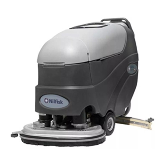
Convertamatic
24, 26, 28, 32
™
BA 625, 725, 825
Service Manual
Advance Models: 56315000(24D-C), 56315001(26D), 56315002(28D),
56315003(24C-C), 56315004(28D-C), 56315005(28C-C), 56315006(X24D-C),
56315007(X24C-C), 56315008(26D-C), 56315009(X26D-C), 56315010(26C-C),
56315011(X26C-C), 56315012(X28D-C), 56315013(X28C-C), 56315804(32D-C)
56315805(X32D-C)
Nilfi sk Models: 56315800(625), 56315801(725), 56315802(725C), 56315803(825)
2/05 revised 4/08 FORM NO. 56043098
Advertisement
Table of Contents
Troubleshooting


Need help?
Do you have a question about the Convertamatic 24 and is the answer not in the manual?
Questions and answers