Nilfisk-Advance HYDRO-RETRIEVER 2052 Service Manual
Hide thumbs
Also See for HYDRO-RETRIEVER 2052:
- Instructions for use manual (38 pages) ,
- Instructions for use manual (37 pages)
Table of Contents
Troubleshooting

Related Manuals for Nilfisk-Advance HYDRO-RETRIEVER 2052


Summary of Contents for Nilfisk-Advance HYDRO-RETRIEVER 2052
- Page 1 Hydro-Retriever 2052 ™ CR 1300 SERVICE MANUAL Advance MODELS 56459504 (battery), 56459505 (battery-Hydro-Max ™ Nilfisk MODELS 56459992 (battery), 56459994 (battery-Hydro-Max ™ 8/99 revised 9/05 Form Number 56043052...
-
Page 2: Table Of Contents
TABLE OF CONTENTS SAFETY INSTRUCTIONS ..............................2 GENERAL INFORMATION .............................. 2-3 OTHER MANUALS ................................3 PARTS & SERVICE STATEMENT ............................ 3 NAME PLATE DATA ................................. 3 TRANSPORTING ................................3 TOWING .................................... 3 JACKING ................................... 3 KNOW YOUR MACHINE ..............................4-5 SPECIFICATIONS AND MAINTENANCE ........................ - Page 3 TABLE OF CONTENTS SQUEEGEE SYSTEM ..............................50-56 FUNCTIONAL OVERVIEW ............................. 50 ELECTRICAL SYSTEM DIAGRAM ..........................50 TROUBLESHOOTING FLOW CHART ........................51-53 SQUEEGEE ADJUSTMENT BEFORE SN1321040 ....................... 54 SQUEEGEE BLADE REPLACEMENT BEFORE SN1321040 ..................55 SQUEEGEE ADJUSTMENT AFTER SN1321039 ......................56 SQUEEGEE BLADE REPLACEMENT AFTER SN1321039 ...................
-
Page 4: Safety Instructions
• This machine is not suitable for picking up hazardous dust. • Use care when using scarifier discs and grinding stones. Nilfisk-Advance will not be held responsible for any damage to floor surfaces caused by scarifiers or grinding stones. •... -
Page 5: Other Manuals
GENERAL INFORMATION OTHER MANUALS AVAILABLE FOR YOUR MACHINE The following manuals are available from the Nilfisk-Advance Literature Service Department (order according to model name and machine’s serial number): • A Parts List and Operation Manual are available for each machine. -
Page 6: Know Your Machine
KNOW YOUR MACHINE Battery Compartment / Recovery Tank Cover Broom Strobe Light Debris Tray Left Rear Access Door (Solution Tank Drain inside door) Inner Access Door Battery Squeegee Solution Tank Fill Vacuum Filter and Housing Circuit Breaker Access Cover Right Rear Access Door Headlights Tip-Out Seat (Access to Differential, Scrub Brushes... -
Page 7: Know Your Machine
KNOW YOUR MACHINE Emergency Battery Disconnect Hour Meter Solution Lever Master Key Switch Broom Lever Forward/Reverse Drive Pedal Squeegee Switch Brake Pedal Solution Switch Horn Scrub Brushes Switch Parking Brake Headlight Switch Hydro-Max™ II Recycle Pump Switch (Opt) Battery Meter Hydro-Max™... -
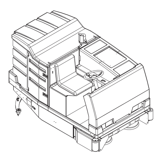
Page 8: Specifications And Maintenance
SPECIFICATIONS AND MAINTENANCE General Machine Specifications English (Metric) Machine Length 89 in. (226 cm) Machine Width w/o Squeegee 54-1/2 in. (138 cm) Machine Height 79 in. (200 cm) with Overhead Guard 56 in. (142 cm) w/o Overhead Guard Machine *Net Weight 1889 lbs. - Page 9 KNOW YOUR MACHINE 79 in. (200 cm) With overhead guard 56 in. (142 cm) Without overhead guard 54.5 in. (138 cm) FRONT VIEW 89 in. (226 cm) SIDE VIEW revised 3/00 FORM NO. 56043052 / HYDRO-RETRIEVER™ 2052, CR 1300 - 7...
-
Page 10: Periodic Maintenance Chart
SPECIFICATIONS AND MAINTENANCE MAINTENANCE SCHEDULE Maintenance intervals given are for average operating conditions. Machines used in severe operational environments may require service more often. MAINTENANCE ITEM DAILY 50 HRS 100 HRS 1000 HRS (YEARLY) Perform the 7 Daily Machine After Use Maintenance Steps * Charge Battery &... -
Page 11: Lubrication
SPECIFICATIONS AND MAINTENANCE BRUSH/BROOM SKIRT INSPECTION Every 50 hours, inspect the rubber skirts all around the machine and in the broom housing; replace if damaged or worn. Reference Sweeping section for more detailed information. VACUUM FILTER MAINTENANCE Every 50 hours, open the Right Rear Access Door (17) and open the small filter door. Remove the filter, rinse in clear water, wring out thoroughly, and put it back into the machine. - Page 12 SPECIFICATIONS AND MAINTENANCE DIFFERENTIAL OIL LEVEL Every 100 hours, check the differential fluid level. Tip the Operator’s Seat (18) forward and remove the dipstick from the tube. Oil level should show about one inch. Add SAE 90W gear oil, if necessary. Do not over-fill! Differential oil capacity is 5 quarts (5.67 liters). GEARBOX OIL LEVEL Check the oil level in the brush drive gear cases once each year or when there is evidence of oil leakage.
- Page 13 SPECIFICATIONS AND MAINTENANCE MOTOR CARBON BRUSH INSPECTION Check the carbon brush wear on the vacuum, scrub, broom and drive motors at least once a year or 1000 hours. If the carbon brush is worn to a length of 3/8 inch (10 mm) or less remove and replace all of the carbon brushes. Reference each separate machine system section in this manual for additional information.
-
Page 14: Battery System
BATTERY SYSTEM BATTERY INSTALLATION WARNING! Use extreme caution when working with batteries. Sulfuric acid in batteries can cause severe injury if allowed to contact the skin or eyes. Explosive hydrogen gas is vented from inside the batteries through openings in the battery caps. This gas can be ignited by any arc, spark or flame. -
Page 15: Maintenance
BATTERY SYSTEM BATTERY MAINTENANCE WARNING! Use extreme caution when working with batteries. Sulfuric acid in batteries can cause severe injury if allowed to contact skin or eyes. Explosive hydrogen gas is vented from inside the battery caps. This gas can be ignited by any electrical arc, spark, or flame. When working with batteries: •... -
Page 16: Battery Charger Specifications
Use a combination of multiple 2-volt cell units to construct a 36 Volt DC battery pack system. Nilfisk-Advance recommended battery pack capacity is a 475 AH @ 6 Hour Rate deep cycle battery system. Note: The battery pack must fit the battery compartment size listed below. -
Page 17: Scrub Brush System
SCRUB BRUSH SYSTEM FUNCTIONAL OVERVIEW The four rotary disc type brushes on the front of the machine are driven by two gear cases coupled together. A single 3HP-(36V) motor mounted on top of the left brush gear case drives the two gear cases. A poly v-belt connects the motor to the input shaft on the left gear case. The input shaft to the left gear case also drives the input shaft on the right case through the use of a flexible coupler. -
Page 18: Scrub Brush Motor Function
SCRUB BRUSH SYSTEM SCRUB BRUSH MOTOR FUNCTION See Figure 3. To energize the K5 brush motor solenoid the S7 brush switch must be on (brushes lowered) and the K9 relay contacts closed. This completes the positive voltage input to the solenoid. The negative input to the solenoid is supplied when the drive pedal is depressed (FWD or REV). -
Page 19: Low Voltage Cut-Out Function
SCRUB BRUSH SYSTEM LOW VOLTAGE CUT-OUT FUNCTION (CONTINUED) Wiring Change Note (Serial Number Break) ™ Note: Hydro-Retriever 2052 machines built after S.N. 1296729 and all CR 1300 machines have the K8 low voltage cutout module input wiring changed. The wiring change turns off the broom and brushes any time the seat switch is opened (operator is off the seat). The addition of the dotted lines shown in Figure 4B illustrates this change. -
Page 20: Troubleshooting Flow Chart
SCRUB BRUSH SYSTEM TROUBLESHOOTING GUIDE Possible Symptoms Brush / Brush Lift / Broom / Solution; do not work Scrub brushes do not turn Scrub brushes do not lower Scrub brushes do not raise SYMPTOM ONE Note: Do all testing with the master key switch ON, seat switch S13 closed, brush switch S7 in the ON position and the parking brake set. Brush / Brush Lift / Broom / Solution Systems;... - Page 21 SCRUB BRUSH SYSTEM TROUBLESHOOTING GUIDE (CONTINUED) SYMPTOM TWO Note: Test with the key switch on, brushes down, parking brake set, seat switch closed and drive pedal slightly depressed (either FWD or REV). Part A: Scrub Brush Motor Load Circuit Troubleshooting Guide Scrub brushes do not turn (see Figure 3).
- Page 22 SCRUB BRUSH SYSTEM TROUBLESHOOTING GUIDE (CONTINUED) SYMPTOM TWO Part B: Scrub Brush Motor Control Circuit Troubleshooting Guide 20 - FORM NO. 56043052 / HYDRO-RETRIEVER™ 2052, CR 1300 revised 3/00...
- Page 23 SCRUB BRUSH SYSTEM TROUBLESHOOTING GUIDE (CONTINUED) SYMPTOM THREE Note: Do all testing with the master key switch ON, brush switch S7 in the ON position and the parking brake set. Scrub brushes do not lower (see Figure 1). Check for 36V at Check for continuity Replace the S11 the M3 lift motor...
- Page 24 SCRUB BRUSH SYSTEM TROUBLESHOOTING GUIDE (CONTINUED) SYMPTOM FOUR Note: Do all testing with the master key switch OFF, brush switch S7 in the ON position and the parking brake set. Scrub brushes do not raise (see Fig. 4) Check for 36V at the Check for continuity Replace the S10 M3 lift motor harness...
-
Page 25: Motor Carbon Brush Inspection & Removal
SCRUB BRUSH SYSTEM MOTOR CARBON BRUSH INSPECTION AND REMOVAL NOTE: The carbon brushes in the scrub brush motor should be inspected once a year or 1000 hours, and any accumulated dust blown out with compressed air. Put the scrub deck in the raised position and turn the key switch OFF. Remove the front outer body fascia panel from the machine (2 screws). -
Page 26: Belt And Gear Box Coupler Removal
SOLUTION SYSTEM BELT AND GEAR BOX COUPLER REMOVAL Put the scrub deck in the raised position and turn the key switch OFF. Remove the front outer body fascia panel from the machine (2 screws). Remove the headlight-mounting panel secured with (6) screws. Then pull the panel out and disconnect wiring and remove. Remove the brush motor spring and put the scrub deck in the lowered position and turn the key OFF and disconnect the battery connector. -
Page 27: Lift Actuator Motor Removal
SCRUB BRUSH SYSTEM LIFT ACTUATOR MOTOR REMOVAL Put the scrub deck in the raised position and turn the key switch OFF. Remove the front outer body fascia panel from the machine (2 screws). Remove the brush motor spring and put the scrub deck in the lowered position and turn the key OFF. Remove the headlight-mounting panel secured with (6) screws. -
Page 28: Front Skirt Adjustment
SCRUB BRUSH SYSTEM FRONT SKIRT ADJUSTMENT The front skirts have 3 functions: To keep water from splashing outside of the squeegee’s path. To wipe water from the floor in front of the drive wheels. To channel debris into the path of the sweeping broom. Adjust or replace the skirts, if they don’t perform any of these functions, using the steps below. -
Page 29: Sweeping System
SWEEPING SYSTEM FUNCTIONAL OVERVIEW Broom System Functional Overview A cylindrical sweeping broom is used to keep small debris out of the squeegee tool blades, eliminating the need to sweep before scrubbing. The debris is lifted over the top of the broom and into a small hopper. The hopper is perforated so that the water, swept up along with the debris can drain back onto the floor to be picked up by the squeegee tool. -
Page 30: Troubleshooting Flow Chart
SWEEPING SYSTEM TROUBLESHOOTING GUIDE Possible Symptoms Broom motor will not run Broom side skirts will not lower Broom side skirts will not raise SYMPTOM ONE Note: Do all testing with the master key switch ON, seat switch closed, broom lever in the ON position and the parking brake set. Part A: Sweeping Broom Motor Load Circuit Troubleshooting Guide Broom motor does not run (see Fig. - Page 31 SWEEPING SYSTEM TROUBLESHOOTING GUIDE (CONTINUED) FIGURE 1 BLK/WHT WHT/VIO YEL/WHT RED/GRN BLU/YEL Motor - Motor - ORN/RED GRN/GRY Motor + Motor + BLK/WHT BLK/WHT Direction Direction (- 36V) (- 36V) Timer Out Timer Out Timer In 1 Timer In 1 Broom On Skirts Lowered Timer In 2 Timer In 2...
- Page 32 SWEEPING SYSTEM TROUBLESHOOTING GUIDE (CONTINUED) SYMPTOM TWO Note: Do all testing with the master key switch ON, seat switch closed, broom lever in the ON position and the parking brake set. Broom side skirts will not lower (see Figure 1) Verify sweep- See symptom ing broom is...
- Page 33 SWEEPING SYSTEM TROUBLESHOOTING GUIDE (CONTINUED) FIGURE 2 BLK/WHT WHT/VIO YEL/WHT RED/GRN BLU/YEL Motor + Motor + ORN/RED GRN/GRY Motor - Motor - BLK/WHT BLK/WHT Direction Direction (0V) (0V) Timer Out Timer Out Timer In 1 Timer In 1 Timer In 2 Timer In 2 Broom Off Skirts Raised SYMPTOM THREE...
-
Page 34: Maintenance
SWEEPING SYSTEM BROOM MAINTENANCE The sweeping broom must be serviced at regular intervals to maintain good sweeping performance. The following maintenance steps should be completed every 50 hours of operation. Note: Side skirts must be in the raised position to fully open broom access door. Clean built-up dirt from the inside of the broom housing. -
Page 35: Broom Level Adjustment
SWEEPING SYSTEM BROOM LEVEL ADJUSTMENT The sweeping broom has a level adjustment to control the height of just the right end of the broom. This allows the broom to be adjusted so that it runs parallel to the floor. The adjustment bolts are located at the right end of the broom, inside the broom access door. Once the broom level is set at the factory, further adjustment is seldom necessary. -
Page 36: Broom Bearing Replacement
SWEEPING SYSTEM BROOM BEARING REPLACEMENT There are sealed ball bearings in the idler hub (on the right end of the broom) and in the drive hub (on the left end of the broom). Whenever the broom is removed for service, these bearings should be checked. Binding, noisy operation or excessive play indicate that the bearings should be replaced. -
Page 37: Broom Motor Removal
SWEEPING SYSTEM BROOM MOTOR REMOVAL Attention read before servicing: Removal method A: Follow steps (1-8) to remove the broom motor when the machine’s battery can be removed. This is the preferred method and needs the proper overhead lift equipment to remove the battery. Removal method B: Follow steps (9-19) when field servicing, when the battery can’t be removed. -
Page 38: Broom Belt Removal/Adjustment
SWEEPING SYSTEM BROOM BELT REMOVAL / ADJUSTMENT Attention: Remove the battery or the recovery tank to allow the needed access for servicing the broom motor belt easily. To remove the broom belt . . . WARNING! Turn the key switch off and disconnect the battery connector before servicing. Lower the sweeping broom to the floor, and then open both the upper and lower left side access doors. -
Page 39: Broom Housing Skirts Replacement & Adjustment
SWEEPING SYSTEM BROOM HOUSING SKIRTS Rubber skirts are installed at the front and the sides of the broom housing to keep debris and water confined to the sweeping area of the machine. For good sweeping performance, all skirts must be in good condition and properly adjusted. The front Skirt (Y) (see Figure 11) keeps litter from being thrown out of the broom housing, once it enters. - Page 40 SWEEPING SYSTEM OUTER SIDE SKIRT ADJUSTMENT Adjust the outer broom housing skirts (LT and RT side) if the machine leaves water on the floor when turning. Inspect the skirts before adjusting; replace them if they are nicked, torn or if the wiping edge is worn to a large radius. To adjust the fold over on the outer skirts (operating position).
-
Page 41: Solution System
SOLUTION SYSTEM FUNCTIONAL OVERVIEW Functional Overview Standard Solution System: A 60-gallon (227 L) capacity solution tank is located to the left of the operator’s compartment. Plumbed to it is an externally mounted serviceable solution filter, to help keep dirt out of the solution valves. The tank is also fitted with a flexible drain hose to facilitate quick draining for system maintenance. -
Page 42: Troubleshooting Guide
SOLUTION SYSTEM FIGURE 2 From Solution Tank Solution On-Off Lever Solution Filter Solution Solenoid Valve Flow Control Valve Main Solution To Brushes Control Valve TROUBLESHOOTING GUIDE Problem Possible Cause Inadequate or no solution flow No solution in the tank Main solution flow control valve lever is in the off position The 2 final output flow control valves are in the off position Clogged solution filter, valves and hoses Defective solution solenoid valve (L1)*... - Page 43 SOLUTION SYSTEM TROUBLESHOOTING GUIDE (CONTINUED) Electrical Symptom Solenoid valve will not open (energize). SYMPTOM NOTE: Test with the key switch on, solution switch on, brushes down, seat switch closed, drive pedal slightly depressed (Fwd or Rev) & parking brake set. *Service Tip: Access the L1 solenoid wiring harness by tipping the seat forward.
-
Page 44: Solution Tank Removal
SOLUTION SYSTEM SOLUTION TANK REMOVAL Drain the solution tank using the drain hose found behind the left rear access door. Turn the master key switch off and disconnect the battery connector before servicing. Remove the front outer body fascia panel from the machine (2 screws) and also remove the headlight panel assembly (6 screws). See Figure 3. -
Page 45: Solution Solenoid Valve & Filter Housing Replacement
SOLUTION SYSTEM SOLUTION SOLENOID VALVE AND FILTER HOUSING REPLACEMENT To access the solenoid valve first drain the solution tank then remove the solution tank from the machine. See solution tank removal section for instructions. See figure 3. Loosen the Hose Clamp (F) and remove the outlet solution Hose (G) at the Solenoid Valve (H). Service Tip Note: The solution hoses can be stubborn (difficult) to separate at their barbed fittings. -
Page 46: Vacuum/Recovery System
VACUUM / RECOVERY SYSTEM FUNCTIONAL OVERVIEW Vacuum / Recovery System General Dirt and water are lifted off the floor into the recovery tank by airflow, created by a 3-Stage 36V vacuum motor. The wastewater and air enter the vacuum system at the squeegee tool, through small openings (notches) located in the front squeegee blade. The small openings are the entrance points for the water and air, and help speed up the airflow producing the suction to lift the wastewater off of the floor. -
Page 47: Electrical System Diagram
VACUUM / RECOVERY SYSTEM FIGURE 2 WHT/BLU WHT/GRN GRA/WHT Motor+ GRN/BRN WHT/BRN Motor- Direction ORN/WHT Timer Out WHT/RED Timer In 1 Timer In 2 WHT/YEL RED/WHT RED/BRN YEL/BRN Forward Throttle Switch Vacuum Motor ON / S6 & S3 Are Closed VACUUM / RECOVERY SYSTEM SERVICE CHECKLIST Whenever there is a vacuum problem, it’s best to check over the entire system. - Page 48 VACUUM / RECOVERY SYSTEM TROUBLESHOOTING GUIDE (CONTINUED) Possible Symptom Vacuum motor will not run SYMPTOM ONE Note: Do all testing with the master key switch ON, seat switch closed, S6 vac/squeegee switch ON (squeegee lowered), the drive pedal depressed in Fwd and the parking brake set. Part A: Vacuum Motor Load Circuit Troubleshooting Guide Vacuum motor will not run (see Figure 2).
- Page 49 VACUUM / RECOVERY SYSTEM TROUBLESHOOTING GUIDE (CONTINUED) SYMPTOM ONE Note: Do all testing with the master key switch ON, seat switch closed, S6 vac/squeegee switch ON (squeegee lowered), the drive pedal depressed in Fwd and the parking brake set. Part B: Vacuum Motor Control Circuit Troubleshooting Guide Vacuum motor will not run (See Figure 2).
-
Page 50: Vacuum Motor Removal
VACUUM / RECOVERY SYSTEM VACUUM MOTOR REMOVAL Turn the key switch OFF and disconnect the battery connector (behind the right rear access door). Lift the operator’s seat and put the prop rod in position to hold it up. Disconnect the vacuum motor wiring connector. See Figure 3. -
Page 51: Recovery Tank Removal
VACUUM / RECOVERY SYSTEM FIGURE 4 Filter Box FRONT Foam Filter FIGURE 5 RECOVERY TANK REMOVAL Recommended Tools: To remove hardware use (1) 7/16-inch combination wrench & (1) 7/16-inch socket wrench. First drain the recovery tank using the side mounted drain hose. Then lift the battery/ recovery compartment cover and position the prop rod to support. -
Page 52: Squeegee System
SQUEEGEE SYSTEM SQUEEGEE LIFT MOTOR SYSTEM GENERAL OVERVIEW The squeegee pick up tool is raised and lowered by an electric actuator motor and cable assembly located at the back of the machine, below the battery and recovery tank. The squeegee lift circuit is controlled by the S6 vacuum/squeegee switch located on the dashboard, the reverse directional switch S2 mounted on the drive pedal linkage and the E2 actuator controller mounted in the left panel electrical box are the system components that manage the functions of the F5 squeegee lift motor. -
Page 53: Troubleshooting Flow Chart
SQUEEGEE SYSTEM TROUBLESHOOTING GUIDE Possible Symptoms Squeegee tool will not lower Squeegee tool will not raise Squeegee tool will not raise in reverse SYMPTOM ONE Note: Test with key switch ON, Vacuum/Squeegee switch S6 ON (lowered position) and the parking brake set. Squeegee tool will not lower. - Page 54 SQUEEGEE SYSTEM TROUBLESHOOTING GUIDE (CONTINUED) SYMPTOM TWO Note: Test with key switch ON, Vacuum/Squeegee switch S6 OFF (raised position) and the parking brake set. Squeegee tool will not raise On the E2 control- Check for zero On the S6 switch ler check for 36V volts at the check for 36V at...
- Page 55 SQUEEGEE SYSTEM TROUBLESHOOTING GUIDE (CONTINUED) SYMPTOM THREE Note: Test with key switch ON, Vacuum/Squeegee switch S6 ON, the reverse S2 switch open by slightly activating the drive in reverse and the parking brake set. Squeegee tool will not raise when in reverse Verify that the squeegee See symptom 2...
-
Page 56: Squeegee Adjustment Before Sn1321040
SQUEEGEE SYSTEM SQUEEGEE ADJUSTMENT FOR MACHINES BEFORE SN1321040 Before adjusting the squeegee . . . Remove the squeegee tool from the machine and inspect the squeegee blades. If the front edge of the wiping blade is worn to a radius, nicked or torn, remove it from the squeegee and turn it around so the edge that used to face forward now faces toward the back of the machine. -
Page 57: Squeegee Blade Replacement Before Sn1321040
SQUEEGEE SYSTEM SQUEEGEE BLADE REPLACEMENT FOR MACHINES BEFORE SN1321040 There are (3) rubber blades on the squeegee. The front blade increases the velocity of the air entering the squeegee. The wiping blade wipes the floor dry. The rear blade supports the wiping blade. The wiping blade works best when there is a sharp corner on its front edge. -
Page 58: Squeegee Adjustment After Sn1321039
SQUEEGEE SYSTEM SQUEEGEE ADJUSTMENT FOR MACHINES AFTER SN1321039 Before adjusting the squeegee . . . Remove the squeegee tool from the machine and inspect the squeegee blades. If the front edge of the wiping blade is worn to a radius, nicked or torn, remove it from the squeegee and turn (or flip) it around so that a sharp edge now faces the front of the machine. -
Page 59: Squeegee Blade Replacement After Sn1321039
SQUEEGEE SYSTEM SQUEEGEE BLADE REPLACEMENT FOR MACHINES AFTER SN1321039 There are (3) rubber blades on the squeegee. The front blade increases the velocity of the air entering the squeegee. The wiping blade wipes the floor dry. The rear blade supports the wiping blade. The wiping blade works best when there is a sharp corner on its front edge. -
Page 60: Squeegee Actuator Lift Motor Replacement
SQUEEGEE SYSTEM SQUEEGEE ACTUATOR LIFT MOTOR REPLACEMENT Turn the key switch off and disconnect the battery connector (inside the right rear door). Remove the recovery tank from the machine (see the recovery tank removal instructions in the Vacuum Recovery section). Reach under the battery, cut wire ties and disconnect the wiring connector for the squeegee lift actuator. -
Page 61: Hydro-Max™ Ii System
™ HYDRO-MAX II SYSTEM FUNCTIONAL OVERVIEW ™ The optional Hydro-Max II system extends the solution’s useful capacity (conserves water usage) by recycling the wastewater picked up from the floor. This allows the machine to scrub continuously, saving time in emptying the recovery tank and refilling the solution tank. The wastewater entering the recovery tank passes through special baffles and filters to remove most of the dirt, then new soap is injected into the treated solution as it is pumped back into the solution tank. - Page 62 ™ HYDRO-MAX II SYSTEM FIGURE 1 Into Solution Tank From Detergent Tank Detergent Float Switches Tank S17 & S18 Metering Barb Pump FRONT FIGURE 3 FIGURE 2 FRONT (closed) (closed) Pump Drain Drain Strainer Screen From Squeegee To Vac Motor RIGHT 60 - FORM NO.
-
Page 63: Ii Recovery Tank Maintenance
™ HYDRO-MAX II SYSTEM ™ HYDRO-MAX II RECOVERY TANK MAINTENANCE IMPORTANT! The recovery tank should be cleaned after each use, in order for Hydro-Max ™ II system to operate properly. To clean the tank… See Figure 3. Use the two Drain Hoses (B) to drain both the recovery tank compartments (one on each side of the tank). Lift out the removable Screen Panel (C) and rinse under running water. -
Page 64: Steering/Brake System
STEERING & BRAKING SYSTEM FUNCTIONAL OVERVIEW Steering System A single steer wheel at the back of the machine is operated by a single chain, which connects the steer wheel spindle to the steering column in the operator’s compartment. The steering system requires little service other then routine lubrication and inspection. Note: See the general maintenance section in this manual for steering lubrication instructions. -
Page 65: Brake Adjustment
STEERING & BRAKING SYSTEM BRAKE ADJUSTMENT Cables are used to connect the brake pedal and the parking brake lever to the brake mechanism on the (2) front wheels. The brake pedal should have about 1 inch (25.4 mm) of down travel before the brakes are fully engaged. If there is too much pedal travel, the brakes should be adjusted. To adjust the brakes . -
Page 66: Wheel Drive System
WHEEL DRIVE SYSTEM FUNCTIONAL OVERVIEW Wheel Drive System The Hydro-Retriever ™ 2052B / CR 1300 is driven by a 4 horsepower permanent magnet motor, coupled to an automotive-type differential. The speed of the motor is regulated by a solid-state speed control (A1), located in the front electrical compartment. A potentiometer (R2), operated by the drive pedal, regulates the speed control. -
Page 67: Electrical System Diagram
WHEEL DRIVE SYSTEM FIGURE 2 FIGURE 3 revised 3/00 FORM NO. 56043052 / HYDRO-RETRIEVER™ 2052, CR 1300 - 65... -
Page 68: Troubleshooting Guide
WHEEL DRIVE SYSTEM TROUBLESHOOTING GUIDE Follow the instructions under the “Symptom” that best describes the condition of the machine being serviced. DANGER! Before troubleshooting the drive system, jack up the machine so the drive wheels are off the floor and place jack stands under the frame. - Page 69 WHEEL DRIVE SYSTEM TROUBLESHOOTING GUIDE (CONTINUED) FIGURE 5 DANGER! Do not attempt to perform the next step with the drive wheels on the floor. The drive motor may run at full speed when the drive pedal is pressed. Jack up the front of the machine, so both drive wheels are off the floor.
- Page 70 WHEEL DRIVE SYSTEM TROUBLESHOOTING GUIDE (CONTINUED) Turn the key switch ON and push down on the operator’s seat while watching the main contactor (see Figure 7). • If the contacts in the main contactor move when the seat is pushed, go to step 6. •...
-
Page 71: No Fwd (Rev Only)
WHEEL DRIVE SYSTEM TROUBLESHOOTING GUIDE (CONTINUED) SYMPTOM TWO: NO FORWARD DRIVE (REVERSE ONLY) DANGER! Before troubleshooting the drive system, jack up the machine so the drive wheels are off the floor and place jack stands under the frame. This will prevent injury if the drive motor starts during testing. Note: All references to “right”... - Page 72 WHEEL DRIVE SYSTEM TROUBLESHOOTING GUIDE (CONTINUED) See Figure 9. Disconnect the diode from the Red/ FIGURE 9 Green wire and connect a DC voltmeter as shown. • If the meter reads 36 volts, replace the diode. • If the meter reads 0 volts, check the forward and reverse switch mechanism (see Forward/Reverse Switch section).
-
Page 73: Wheel Motor Removal
WHEEL DRIVE SYSTEM TROUBLESHOOTING GUIDE (CONTINUED) FIGURE 11 See Figure 11. Disconnect the diode from the Red/ Green wire and connect a DC voltmeter as shown. • If the meter reads 36 volts, replace the diode. • If the meter reads o volts, check the forward and reverse switch mechanism (see Forward/Reverse Switch section). -
Page 74: Differential Removal
WHEEL DRIVE SYSTEM DIFFERENTIAL REMOVAL Remove the solution tank (see Solution System for instructions). Remove the wheel drive motor (see Wheel Motor Removal section for instructions). Loosen the lug nuts on both front wheels. Then jack up the front of the machine so the wheels are about 1-1/2 inches (38 mm) off the floor. WARNING! Never work under the machine without jack stands or blocks supporting the frame. -
Page 75: Speed Potentiometer Replacement
WHEEL DRIVE SYSTEM FORWARD & REVERSE SWITCH ADJUSTMENT & REPLACEMENT (CONTINUED) To replace the forward, reverse & squeegee switches… See Figure 14. Remove the front access panel and remove the (2) Screws (J). Pull switch bracket (K) out of the compartment as far as the attached linkage will allow and remove the switch needing replacement. Install the new switch (or switches) but do not tighten the mounting screws. -
Page 76: Speed Potentiometer Adjustment
WHEEL DRIVE SYSTEM SPEED POTENTIOMETER ADJUSTMENT Before adjusting the potentiometer . . . • Gently move the front of the drive pedal up and down in neutral, to check the free travel in the pedal. If there is more than 1/8 inch (3 mm) free travel at the front of the drive pedal, adjust Bracket (H) (see Figure 14) up or down to eliminate the free travel. -
Page 77: Electrical System
ELECTRICAL SYSTEM ACTUATOR DRIVE NUT ADJUSTMENT This manual section explains the steps for adjusting the drive nut settings for all three of the machine’s lift actuator motors. Reference the chart below to find the In & Out dimensional specification for the specific actuator motor needing adjustment. Part # Actuator Motor Drive Nut In Position... -
Page 78: Electrical Component Location Diagram
ELECTRICAL SYSTEM ELECTRICAL COMPONENTS Circuit Breaker, 10 Amp (Aux. 2 / F7) Circuit Breaker, 5 Amp (Drive Control Circuit / F5) Circuit Breaker, 80 Amp (Brush Motor / F1) Circuit Breaker, 40 Amp (Vac Motor / F2) Circuit Breaker, 15 Amp (Aux. 1 / F4) Circuit Breaker, 40 Amp (Broom Motor / F3) Relay (Low Voltage Cut-Out / K9) Dual Control Assembly... - Page 79 ELECTRICAL SYSTEM COMPONENT LOCATION Item Description H6 - Horn L1 - Solution Solenoid M1 - Broom Motor " M2 - Recycle Pump Motor (Hydro-Max II) M3 - Brush Lift Actuator M4 - Brush Motor M5 - Squeegee Lift Actuator M6 - Vacuum Motor M7 - Wheel Drive Motor M8 - Left Side Skirt Lift Actuator M9 - Right Side Skirt Lift Actuator...
-
Page 80: Electrical Schematic And Wiring Diagrams Before Sn 1296730
ELECTRICAL SYSTEM SCHEMATIC / WIRING DIAGRAM FOR HYDRO-RETRIEVER ™ 2052 MACHINES BUILT BEFORE SN 1296730 RED/BLK Item Description Item Description BRN/BLK Speed Controller Solution Solenoid YEL/RED GRN WIRE NOT USED YEL/RED YEL/RED Suppression Diode Broom Motor Suppression Diode Recycle Pump Motor (Hydro-Max II) Suppression Diode Brush Lift Actuator Blocking Diode... - Page 81 ELECTRICAL SYSTEM FOR HYDRO-RETRIEVER ™ 2052 MACHINES BEFORE SN 1296730 X1 1 S 1 7 R E D O R N /R E D 3 2 B -A G R A /W H T 8 9 B -B W H T /B R N 9 1 B -B S 1 8 B L K R E D /G R N 2 5 B -A...
-
Page 82: Electrical Schematic And Wiring Diagrams After Sn 1296729
ELECTRICAL SYSTEM SCHEMATIC / WIRING DIAGRAM FOR HYDRO-RETRIEVER ™ 2052 RED/BLK BRN/BLK MACHINES AFTER SN 1296729 AND ALL CR 1300 MACHINES RED/BRN YEL/RED Item Description Item Description GRN WIRE NOT USED YEL/RED YEL/RED Speed Controller Solution Solenoid Suppression Diode Broom Motor Suppression Diode BRN/YEL Recycle Pump Motor (Hydro-Max II) -
Page 83: Electrical System
™ FOR HYDRO-RETRIEVER 2052 MACHINES AFTER SN 1296729 AND ALL CR 1300 MACHINES ELECTRICAL SYSTEM X1 1 S 1 7 R E D O R N /R E D 3 2 B -A G R A /W H T 89B -B W H T /B R N 91B -B S 1 8 B LK... - Page 86 Austria (Sales Sub) Holland (Sales Sub) Nilfi sk-Advance GmbH Phone: +43 Nilfi sk-Advance B.V. Phone: +31 Voralberger Allee 46 1616 58 30 22 Camerastraat 9 (2e verdieping) 36 546 07 00 A-1230 Wien Fax: +43 1322 BB Almere Fax: +31 info@nilfi...
- Page 87 Sweden (Prod.) Hong Kong (Sales Sub) Nilfi sk-Advance A/S Phone: +46 Nilfi sk-Advance Ltd. Phone: +852 Åmål Branch 5321 7500 2001 HK Worsted Mills Ind’l Bldg., 2427 5951 Strömsbergsgatan Fax: +46 31-39 Wo Tong Tsui St. Fax: +852 Box 127 5321 7595 Kwai Chung, Hong Kong 2487 5828...
- Page 88 www.nilfi sk-advance.com © 2005...
Need help?
Do you have a question about the HYDRO-RETRIEVER 2052 and is the answer not in the manual?
Questions and answers