Table of Contents
Advertisement
NOTICE: SAVE THESE INSTRUCTIONS
Mo d el ( s ) :
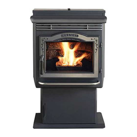
PP38+ Freestanding Pellet Stove
PLEASE READ TH iS ENTiRE MANUAL BEFORE YOU iNSTALL AND USE YOUR NEW
FOLLOW
iNSTRUCTiONS MAY RESULT iN PROPERTY DAMAGE, BODiLY iNJURY, OR EVEN DEATH .
FOR USE iN TH E U. S. AND CANADA. SUiTABLE FOR iNSTALLATiON iN MOBiLE H OMES.
iF TH iS H ARMAN STOVE iS NOT PROPERLY iNSTALLED, A H OUSE FiRE MAY RESULT. FOR YOUR SAFETY, FOLLOW
iNSTALLATiON DiRECTiONS.
CONTACT LOCAL BUiLDiNG OR FiRE OFFiCiALS ABOUT RESTRiCTiONS AND iNSTALLATiON iNSPECTiON
REQ UiREMENTS iN YOUR AREA.
CONTACT YOUR LOCAL AUTH ORiTY ( SUCH AS MUNiCiPAL BUiLDiNG DEPARTMENT, FiRE DEPARTMENT, FiRE
PREVENTiON BUREAU, ETC. ) TO DETERMiNE TH E NEED FOR A PERMiT.
CETTE GUiDE D' UTiLiSATiON EST DiSPONiBLE EN FRANCAiS. CH EZ VOTRE CONCESSiONNAiRE DE H ARMAN
H OME H EATiNG.
in s t a l l a t i o n & Op er a t i n g Ma n u a l
SAFETY NOTiCE
SAVE TH ESE iNSTRUCTiONS.
H o t g l a s s w i l l c a u s e b u r n s .
• Do not touch glass until it is cooled
• NEVER allow children to touch glass
• Keep children away
• CAREFULLY SUPERVISE children in same room as
stove.
• Alert children and adults to hazards of high temperatures.
H i g h t e m p e r a t u r e s m a y i g n i t e c l o t h i n g o r o t h e r
flammable materials.
• Keep clothing, furniture, draperies and other flammable
materials away.
To obtain a French translation of this manual, please
contact your dealer or visit www.harmanstoves.com
Pour obtenir une traduction française de ce manuel, s'il
vous plaît contacter votre revendeur ou visitez www.
harmanstoves.com
Contact your local dealer with questions on installation,
operation or service.
!
WARNING
H OT SURFACES!
Glass and other surfaces are hot during
operation and cool down.
NOTE
ROOM H EATER. FAiLURE TO
3-90-08422R34_08/13
Advertisement
Table of Contents

Related Manuals for Harman PP38 plus


Summary of Contents for Harman PP38 plus
-
Page 1: Safety Notice
in s t a l l a t i o n & Op er a t i n g Ma n u a l NOTICE: SAVE THESE INSTRUCTIONS WARNING H OT SURFACES! Glass and other surfaces are hot during operation and cool down. H o t g l a s s w i l l c a u s e b u r n s . Mo d el ( s ) : • Do not touch glass until it is cooled PP38+ Freestanding Pellet Stove... - Page 2 7 6 m m m i n 3" m i n 9"(228mm) 3-90-08422R34_08/13 PP38+ Pellet Stove...
-
Page 3: Table Of Contents
in t r o d u c t i o n Ta b l e o f Co n t en t s W ARNiNG DO NOT CONNECT TO ANY AiR DiSTRiBUTiON DUCT OR SYSTEM. Safety Information Installation W ARNiNG Venting DO NOT USE C H EMiCALS OR FLUiDS TO START T H E ... -
Page 4: Safety Information
iMPORTANT NOTES W ARNiNG DO NOT iNSTALL A FLUE DAMPER iN TH E EX H AUST VENTiNG SYSTEM OF TH iS UNiT. MOBiLE/ MANUFACTURED H OME STANDARDS DO NOT ALLO W iNSTALLATiON iN ROOMS DESiGNATED FOR SLEEPiNG. DO NOT CONNECT TH iS UNiT TO A CH iMNEY FLUE SERViNG ANOTH ER APPLiANCE. -
Page 5: Installation
As s em b l y a n d in s t a l l a t i o n Un p a c k i n g The P38 is bolted (1/4 x 1" hex head bolts) to the skid to prevent movement during shipping. To free the stove from the skid you must remove the hold- down bolts in the rear of the pedestal base. Route Room Sensor cable through here. Rem o vi n g r ea r c o ver p a n el s The rear cover panels are secured to the stove with three bolts each. Two of the bolts need only be loosened, not removed, to remove the panels. It is recommended that the... - Page 6 in s t a l l a t i o n in s t a l l i n g Alternate floor protector Place the stove on a noncombustible type floor or floor protector dimension may be used as long as they satisfy the that extends a minimum of 6 inches (152mm) to the front of the 9"(228mm) measurement requirements load door opening, 6 inches (152mm) to the sides of the door shown below. opening, and 6 inches to the rear. Floor protection must also M i n u m u m s i z e f l o o r extend 2 inches (51mm) beyond each side of any horizontal flue...
-
Page 7: Venting
Ven t i n g Req u i r em en t s f o r Ter m i n a t i n g t h e Ven t i n g I. The clearance to service regulator vent outlet must be a minimum of 6 feet. W ARNiNG: Venting terminals must not be recessed into a wall or siding. J. The clearance to a non-mechanical air supply inlet to the building or the combustion air inlet to any other appliance NOTE: Only approved pellet vent pipe, wall pass-throughs,... - Page 8 Ven t i n g Ven t Pi p e iMPORTANT NOTiCE Pellet venting pipe (known as PL vent) is constructed of two Approved 3" or 4" Pellet Vent Pipe Such As, Type "PL", layers with air space between the layers. This air space acts Must Be Used. as an insulator and reduces the outside surface temperature to allow a clearance to combustibles of 1 to 3 inches. The sections of pipe lock together to form an air tight seal in most cases. However, in some cases a perfect seal is not achieved. For this reason and the fact that the unit operates with a positive vent pressure w e s p e c i f y t h a t t h e j o i n t s a l s o b e s ea l ed w i t h h i g h t em p ( RTV) s i l i c o n e.
- Page 9 Ven t i n g Per national building codes, consideration must be given to combustion air supply to all combustion appliances. Failure to supply adequate combustion air for all appliance demands, may lead to back-drafting of those and other appliances. Outside air flex pipe goes here. When the appliance is side-wall vented: The air intake is best located on the same exterior wall as the exhaust vent outlet and located lower on the wall than the exhaust vent outlet. When the appliance is roof vented: The air intake is best located on the exterior wall oriented towards the prevailing wind direction during the heating season. The outside air connection will supply the demands of the pellet appliance, but consideration must be given to the total house demand. House demand may consume some air needed for the stove, especially during a power failure. It may be necessary to add additional ventilation to the space in...
- Page 10 Ven t i n g # 1 Pr ef er r ed m et h o d This method provides excellent venting for normal operation and allows the stove to be installed closest to the wall. Two inches from the wall is safe; however, four inches allows better access to remove the rear panel. The vertical portion of the vent should be three to five feet high. This vertical section will help provide natural draft in the event of a power failure. No t e: Do n o t p l a c e j o i n t s w i t h i n w a l l p a s s - t h r o u g h s . 3 f t .
-
Page 11: Installing Into An Existing Fireplace Chimney
Ven t i n g # 4 in s t a l l i n g i n t o a n ex i s t i n g c h i m n ey This method provides excellent venting for normal operation. This method also provides natural draft in the event of a power failure. If the chimney condition is questionable* you may want to install a liner as in method #7. - Page 12 Ven t i n g #6 Installing into an existing fireplace chimney This method provides excellent venting for normal operation. This method also provides natural draft in the event of a power failure. In some places in the US and Canada it is required that the vent pipe extend all the way to the top of the chimney. The pipe or liner inside the chimney should be 4" diameter. In this method a cap should also be installed on the chimney to keep out rain. Be sure to use approved pellet vent pipe fittings. Seal pipe joints with silicone or aluminum tape in addition to the sealing system used by the manufacturer. Pipe size should be increased to 4" using this method.
- Page 13 Ven t i n g Storm collar Flashing 3" min. 3" min. 3" min. PL vent manufacturer's firestop spacer and support Minimum flue vent configuration N o i n s u l a t i o n o r It is required that outside air other combustible materials are allowed be installed with this venting...
-
Page 14: Esp Control
Dealer Diagnostic Port For dealer maintenance only. Requires special DDM monitor supplied to Harman Dealers exclusively. St a t u s Li g h t Er r o r Mes s a g es 6 - Bl i n k s : Indicates the control has measured incomplete combustion ocurring for more than 25 minutes. This error... -
Page 15: Operation
OPERATiON The PP38+ features two operating modes; St o ve Tem p er a t u r e Ro o m Tem p er a t u r e Mo d e Mo d e and Ro o m Tem p er a t u r e Mo d e. In Stove Temperature Mode, you select a burn rate and the stove will remain at the same burn rate regardless of the room temperature. - Page 16 OPERATiON St o ve Tem p er a t u r e Mo d e St o ve Tem p er a t u r e Mo d e In the Stove Temperature Mode, the stove can be adjusted to the desired setting using the same temperature control dial as is used in the Room Temperature Mode. The heat output and fuel consumption will remain constant regardless of room temperature. The settings from 1 to 7 on the inner ring of the temperature dial provide for relative heat output settings with 1 being low and 7 being the maximum. Never pull the plug to shut down the stove. This will stop the combustion blower and smoke will escape through window and door gaskets. Feed Ad j u s t er K n o b For most premium grade pellet fuels the Feed Adjuster Knob should be set at 4. If higher ash fuels are used the setting should be increased to 5 or 6. Also higher settings are...
- Page 17 OPERATiON St a r t i n g Fi r s t Fi r e Make sure the unit is plugged into a 120 VAC, 60 HZ electrical source. The power light should be the only light lit. NOTiCE: Be s u r e t h er e i s n o u n b u r n ed f u el o r o t h er c o m b u s t i b l es i n t h e a s h p a n p r i o r t o l i g h t i n g .
-
Page 18: Draft Test Procedure
Dr a f t Tes t Pr o c ed u r e A simple draft test should be performed before and after completing the flue pipe installation. To compare and to record the results for future reference: 1. Plug the unit into a 120 VAC, 60 HZ outlet. 2. Close the hopper lid, front view door, and the ash pan. Neither pellets or a fire are required for this test. 3. With the mode selector in the "OFF" position, turn the feed adjuster to "TEST". 4. Record the high draft______in W.C. (Normal is -.50 to -.60) The control will be on the High Draft for a minute. -
Page 19: Maintenance
A professional chimney sweep is recommended, since they would normally have the correct equipment to ensure proper creosote removal. If you experience a fire in the venting system, turn the stove to "OFF" to allow the unit to shut down. Call the fire department, and be sure everyone is out of the residence. Before re-using the appliance, have it, and the venting system thoroughly inspected and replace any damaged components. The glass in your Harman stove is a special 5mm ceramic glass. Glass • Do not abuse the glass by striking or slamming Retainers and screws the door. •... - Page 20 Ma i n t en a n c e Sc r a p i n g t h e b u r n p o t : Whenever adding fuel to the hopper, take the time and scrape the grate surface of the burnpot, using the scraper tool provided. This can be done while a fire is burning. Wearing heat resistant gloves, open the firebox door. Scrape any accumulated ashes from in front of the fire, into the ash pan. Now, scrape under the fire, in a downward direction, to loosen any carbon deposits. Do not scrape the fire out of the...
- Page 21 Ma i n t en a n c e 6. Remove the ash pan and properly dispose of the ashes. 7. Remove combustion blower cover by turning the blower cover latch vertical, see Fig.26. Sliding the cover out of the slot on the left. This will expose the combustion blower wheel and flue outlet, Fig.27. 8. Clean the combustion blower wheel with a brush and a Burn pot Clean-out vacuum cleaner. Note: Do not use a household vacuum plate to clean the stove. We recommend that you use a shop vacuum that is equipped with a fine dust filter called a HEPA filter or a vacuum specially made for ashes and soot. Us i n g a va c u u m w h i c h i s n o t eq u i p p ed w i t h a Fi g .
- Page 22 Ma i n t en a n c e - Bu r n Po t Bu r n Po t Cl ea n i n g a n d Ma i n t en a n c e 1. Scrape the top holed surface and sides of the burn pot. (Fig 33) It is not necessary to completely remove all material from the burn pot. The excess will be pushed out during the next use.
- Page 23 Ma i n t en a n c e - Cl ea n i n g t h e Feed er Bo d y Pellet fines may accumulate in the feeder body over a period of time; therefore, a yearly inspection and cleaning of this area must be performed. To clean out fines: 5/16" Hex Head 1. Remove the rear cover panels. 5/16" Hex Head Screws (2 on Screws (2 on each side) 2. Remove wing nut and feeder cover on the side of the each side)
-
Page 24: Troubleshooting
Tr o u b l e- Sh o o t i n g STOVE DOES NOT FEED SMOK E iS ViSiBLE COMiNG OUT OF VENT 1. No fuel in hopper. 1. Air-fuel ratio is too rich. 2. Firebox draft may be too low for sensing switch in feeder a. Feed rate too high. circuit to operate. C h e c k f o r c l o s e d d o o r s , loose or b. Draft too low caused by a gasket leak. -
Page 25: Specifications
Specifications 22" " W ei g h t 212 l b s . Bl o w er 135 c f m Feed Ra t e a p p r o x i m a t e . 7 5l b . t o 5. 5 l b s p er h r H o p p er Ca p a c i t y 50 l b s Fu el... -
Page 26: Options
Op t i o n s Si d e H ea t Sh i el d s -Part #1-00-773863 Di r ec t Ven t W a l l Pa s s t h r o u g h K i t Side heat shields are available to reduce the clearance to You may choose to use the optional Direct Vent Wall combustible materials. -
Page 27: Corn/Pellet Mixture
Addendum for Burning Corn and Pellet Fuel Mixture Harman pellet burning, free-standing stoves and inserts have been tested to ASTM E1509 for burning shelled corn in a mixture with wood pellets. The listing approves up to a 50% corn and 50% pellet mixture. Di erent mixtures of corn will have distinctively di erent burn characteristics depending upon moisture content and variety. -
Page 28: Fuel Specification Details
Fuel Specifications Fu el a n d Fu el St o r a g e Size Pellet fuel quality can fluctuate from manufacturer to • Pellets are either 1/4 inch or 5/16 inch (6-8mm) in manufacturer, and even from bag to bag. diameter Hearth & Home Technologies recommends using only fuel • Length should be no more than 1-1/2 inches (38mm) that is certified by the Pellet Fuels Institute (PFI). -
Page 29: Wiring Diagram
W i r i n g Di a g r a m P P 38+ P e l l e t S t o v e 3-90-08422R34_08/13... -
Page 30: Warranty
H ea r t h & H o m e Tec h n o l o g i es LiMiTED LiFETiME W ARRANTY Hearth & Home Technologies, on behalf of its hearth brands (”HHT”), extends the following warranty for HHT gas, wood, pellet, coal and electric hearth appliances that are purchased from an HHT authorized dealer. W ARRANTY COVERAGE: HHT warrants to the original owner of the HHT appliance at the site of installation, and to any transferee taking ownership of the appliance at the site of installation within two years following the date of original purchase, that the HHT appliance will be free from defects in materials and workmanship at the time of manufacture. After installation, if covered compo- nents manufactured by HHT are found to be defective in materials or workmanship during the applicable warranty period, HHT will, at its option, repair or replace the covered components. HHT, at its own discretion, may fully discharge all of its obligations under such warranties by replacing the product itself or refunding the verified purchase price of the product itself. The maximum amount recoverable under this warranty is limited to the purchase price of the product. This warranty is subject to conditions, exclusions and limitations as described below. W ARRANTY PERiOD: Warranty coverage begins on the date of original purchase. In the case of new home construction, warranty coverage begins on the date of first occupancy of the dwelling or six months after the sale of the product by an independent, authorized HHT dealer/ distributor, whichever occurs earlier. The warranty shall commence no later than 24 months following the date of product shipment from HHT, regardless of the installation or occupancy date. The warranty period for... -
Page 31: Warranty Conditions
warrantY conditions: • This warranty only covers HHT appliances that are purchased through an HHT authorized dealer or distributor. A list of HHT authorized dealers is available on the HHT branded websites. • This warranty is only valid while the HHT appliance remains at the site of original installation. • This warranty is only valid in the country in which the HHT authorized dealer or distributor that sold the appliance resides. • Contact your installing dealer for warranty service. If the installing dealer is unable to provide necessary parts, contact the nearest HHT authorized dealer or supplier. Additional service fees may apply if you are seeking warranty service from a dealer other than the dealer from whom you originally purchased the product. • Check with your dealer in advance for any costs to you when arranging a warranty call. Travel and shipping charges for parts are not covered by this warranty. warrantY eXclusions: This warranty does not cover the following: • Changes in surface finishes as a result of normal use. As a heating appliance, some changes in color of interior and exterior surface finishes may occur. This is not a flaw and is not covered under warranty. • Damage to printed, plated, or enameled surfaces caused by fingerprints, accidents, misuse, scratches, melted items, or other external sources and residues left on the plated surfaces from the use of abrasive cleaners or polishes. • Repair or replacement of parts that are subject to normal wear and tear during the warranty period. These parts include: paint, wood, pellet and coal gaskets, firebricks, grates, flame guides, batteries and the discoloration of glass. • Minor expansion, contraction, or movement of certain parts causing noise. These conditions are normal and com- plaints related to this noise are not covered by this warranty. • Damages resulting from: (1) failure to install, operate, or maintain the appliance in accordance with the installation instructions, operating instructions, and listing agent identification label furnished with the appliance; (2) failure to install the appliance in accordance with local building codes; (3) shipping or improper handling; (4) improper opera- tion, abuse, misuse, continued operation with damaged, corroded or failed components, accident, or improperly/ incorrectly performed repairs; (5) environmental conditions, inadequate ventilation, negative pressure, or drafting caused by tightly sealed constructions, insufficient make-up air supply, or handling devices such as exhaust fans or forced air furnaces or other such causes; (6) use of fuels other than those specified in the operating instructions; (7) installation or use of components not supplied with the appliance or any other components not expressly authorized and approved by HHT; (8) modification of the appliance not expressly authorized and approved by HHT in writing;... -
Page 32: Service Parts
P38 Pel l et Ser vi c e Pa r t s St eel Pel l et St o ve Beg i n n i n g Ma n u f a c t u r i n g Da t e: N/ A En d i n g Ma n u f a c t u r i n g Da t e: Ac t i ve 1- 9 0- 08500- 1 ( Bl a c k ) , Ret i r ed Un i t s... - Page 33 P38 Pel l et Ser vi c e Pa r t s Beg i n n i n g Ma n u f a c t u r i n g Da t e: N/ A En d i n g Ma n u f a c t u r i n g Da t e: Ac t i ve IMPORTANT: THIS IS DATED INFORMATION. Parts must be ordered from a dealer or distributor.
- Page 34 P38 Pel l et Ser vi c e Pa r t s Beg i n n i n g Ma n u f a c t u r i n g Da t e: N/ A En d i n g Ma n u f a c t u r i n g Da t e: Ac t i ve # 2 Pr e Ser i a l Nu m b er 00808006 6 Feed er As s em b l y 2.
- Page 35 P38 Pel l et Ser vi c e Pa r t s Beg i n n i n g Ma n u f a c t u r i n g Da t e: N/ A En d i n g Ma n u f a c t u r i n g Da t e: Ac t i ve # 3 Po s t Ser i a l Nu m b er 00808006 6 Feed er As s em b l y 3.
- Page 36 P38 Pel l et Ser vi c e Pa r t s Beg i n n i n g Ma n u f a c t u r i n g Da t e: N/ A En d i n g Ma n u f a c t u r i n g Da t e: Ac t i ve IMPORTANT: THIS IS DATED INFORMATION. Parts must be ordered from a dealer or distributor.
- Page 37 Ser vi c e & Ma i n t en a n c e Lo g Date Of Service Performed By Description Of Service P P 38+ P e l l e t S t o v e 3-90-08422R34_08/13...
- Page 38 At Harman, we build each product to a standard, not a price. This powerful heating appliance boasts uncompromising attention to detail and helps preserve our planet by using environmentally responsible fuels. (Signature of Boxer) Your premium quality hearth product designed and assembled by the experienced and skilled members at Harman in Halifax, PA, USA.
Need help?
Do you have a question about the PP38 plus and is the answer not in the manual?
Questions and answers