Harman P35i Instructions Manual
Zero clearance cabinet
Hide thumbs
Also See for P35i:
- Owner's manual (50 pages) ,
- Owner's manual installation and operation (50 pages) ,
- Owner's manual (48 pages)
Advertisement
Quick Links
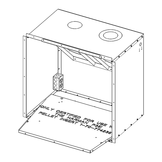
P35i Zero Clearance Cabinet Instructions
Part #1-00-774257
Assembly Instructions:
Contents of Kit;
(1) Top Panel
(1) Bottom Panel
(2) Side Panels
(1) Rear Panel
(1) Flue Pipe Insulation Wrap
(2) Wire Wraps
(48) #8 X 1/2" Tek Screws (Self-Tapping)
Dimensions
8-1/4"
(210mm)
24-3/4"
(629mm)
1
Tools Needed;
Cordless Drill or Screw gun
1/4" Driver Bit
Small pair of "C clamp" locking
pliers are helpful.
26-1/2"
(673mm)
7-5/16"
(186mm)
Ø 3-7/8"
Ø 6-1/16"
98mm
156mm
28-1/16"
(714mm)
5-1/4"
(133mm)
16-15/16"
(430mm)
7-7/8"
(200mm)
1"
(25mm)
24-3/4"
(629mm)
3-90-774256_R4 • 03/21
Advertisement

Related Manuals for Harman P35i


Summary of Contents for Harman P35i
- Page 1 P35i Zero Clearance Cabinet Instructions Part #1-00-774257 Assembly Instructions: Tools Needed; Cordless Drill or Screw gun Contents of Kit; 1/4” Driver Bit (1) Top Panel Small pair of “C clamp” locking (1) Bottom Panel pliers are helpful. (2) Side Panels...
- Page 2 ZC Box Assembly CAUTION Use care when installing tek screws, do not strip the holes. • Begin with the bottom panel lying flat on the floor or workbench. Place it with the writing facing upward. Figure 1. Bend on top goes outside the side panels.
- Page 3 Electrical Installation Flue Rough-In Support Kit (If Needed) A knockout is provided in the left rear corner of the zero Flue rough-in support #1-00-774283 installs in the zero clearance cabinet to install an electrical outlet (not supplied) clearance cabinet and provides a flue stub mounting surface if desired. Be sure to ground the receptacle to the zero which will be in the exact position of the stub when it is on clearance cabinet if installed.
- Page 4 Framing • The flange around the front of the cabinet must mate up to the finished face. Use the holes in the flange to secure the cabinet. Alternately, extra mounting holes can be drilled through the cabinet where desired. Figure 5. Framing and other combustible Follow vent manufacturers materials are permitted to touch the guidelines and maintain proper outside walls of the cabinet. clearance to combustibles.
- Page 5 Raised Hearth Installation When constructing with a raised hearth, be sure to build in support for the cabinet. This floor material can be used under the cabinet only, or it can be applied onto the hearth as well. The image at right shows 3/4” plywood extending onto the hearth. Notice the support members at the front and rear of the cabinet. The hearth finish material cannot exceed 1/4” above the top edge of the cabinet base. See detail below. Also remember, the hearth needs to extend to provide the proper combustible floor protection. Figure 7.
- Page 6 Venting Follow vent manufacturers guidelines and maintain proper clearance to combustibles. Must use an approved wall pass-through or thimble where venting penetrates an external wall. You must use a minimum 12” vertical section of vent pipe attached to the flue stub. Vent pipe within cabinet must be wrapped with the included insulation to prevent overheating of motors and components.
Need help?
Do you have a question about the P35i and is the answer not in the manual?
Questions and answers