Table of Contents
Advertisement
Quick Links
Advertisement
Table of Contents

Related Manuals for Omega HHM29


Summary of Contents for Omega HHM29
- Page 1 OMEGA...
- Page 2 European New Approach Directives. OMEGA will add the CE mark to every appropriate device upon certification. The information contained in this document is believed to be correct but OMEGA Engineering, Inc. accepts no liability for any errors it contains, and reserves the right to alter specifications without notice.
-
Page 3: Safety Information
SAFETY INFORMATION The following safety information must be observed to insure maximum personal safety during the operation at this meter: 1. Do not use the meter if the meter or test leads look damaged, or if you suspect that the meter is not operating properly. 2. -
Page 4: Specifications
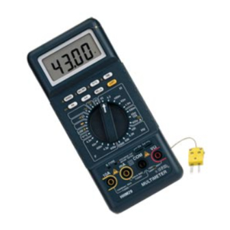
SPECIFICATIONS Display: Liquid crystal display (LCD) with a maximum reading of 4300. Polarity: Automatic, positive implied, negative polarity indication. Overrange: "1 OL"or "-1 OL" is displayed. Low battery indication: The " " is displayed when the battery voltage drops below the operating level. Measurement rate: 2.5 times per second, nominal. - Page 5 DC VOLTS Ranges: 430mV,4.3V,43V,430V,1000V Resolution: 100µV Accuracy: ±(0.25%rdg + 1dgt) Input impedance: >10MW Overload protection: 1000VDC or 750VAC rms AC VOLTS (50Hz-2KHz) Ranges: 430mV,4.3V,43V,430V,750V Resolution: 100µV Accuracy: Range 50Hz-100Hz 100Hz-500Hz 500Hz-2KHz 430mV ±(1.5%rdg+3dgts) 4.3V ±(0.75%rdg+2dgts) 430V ±(1.5%rdg+3dgts) 750V Input impedance: >10MW Overload protection: 1000VDC or 750VAC rms...
- Page 6 DC CURRENT Ranges: 430µA,43mA,430mA,10A Resolution: 100nA Accuracy: ±(0.5%rdg + 1dgt) on 430µA,43mA ranges ±(2.0%rdg + 1dgt) on 430mA,10A ranges Burden voltage: 1.4V on all ranges, execpt 1.5V on 10A range Input protection: 0.5A / 250V fast blow fuse 10A / 600V fast blow ceramic fuse AC CURRENT (50Hz-1KHz) Ranges: 430µA,43mA,430mA,10A Resolution: 100nA...
- Page 7 CONTINUITY Audible indication: <50W ±30W Overload protection: 500VDC or AC rms DIODE TEST Accuracy: ±(3.0%rdg + 3dgts) Resolution: 1mV Test current: 1.0±0.6mA Test voltage: <3.5V LOGIC TEST Threshold:Logic Hi( ) (2.8 ± 0.8V) Logic Lo( ) (0.8 ± 0.5V) Frequency response: 20MHz Detectable pulse width: 25nS Pulse limits: >30% &...
- Page 8 FREQUENCY Ranges: 430Hz,4.3KHz,43KHz,430KHz Resolution: 0.1Hz Accuracy: ±(1.0%rdg + 3dgts) @5V Sensitivity: 500mV Overload protection: 500VDC or AC rms CAPACITANCE Ranges: 4.3nF,43nF,430nF,4.3µF,430µF Resolution: 1pF Accuracy: ±(5.0%rdg + 10dgts) Test frequency: 4300pF,43nF ranges 1KHz 430nF,4.3µF ranges 270Hz 430µF range 27Hz INDUCTANCE Ranges: 4.3mH,43mH,430mH,4.3H,43H Resolution: 1µH Accuracy: ±(5.0%rdg + 20dgts) on 4.3mH range ±(5.0%rdg + 10dgts) on 43mH to 43H ranges...
-
Page 9: Operation
OPERATION Before taking any measurements, read the Safety Information Section. Always examine the instrument for damage, contamination (excessive dirt, grease, etc.) and defects. Examine the test leads for cracked or frayed insulation. If any abnormal conditions exist do not attempt to make any measurements. - Page 10 A-H Button In Auto hold mode, the meter will capture and hold the first stable non- zero(>100 digits) reading after a zero reading(<100 digits). Several consecu- tive measurements can be held and displayed without pressing the (A-H) buttion. Simply by shorting the test leads together between measurements. Press (A-H) to toggle in and out of the Auto Hold mode.
- Page 11 Voltage Measurements 1. Connect the red test lead to the "VW " jack and the black test lead to the "COM" jack. 2. Set the Function/Range switch to the desired voltage function. 3. Connect the test leads to the device or circuit being measured. 4.
- Page 12 Diode Tests 1. Connect the red test lead to the "VW " jack and the black test lead to the "COM" jack. 2. Set the Function/Range switch to the " " position. 3. Turn off power to the circuit under test. 4.
- Page 13 Inductance Measurements 1. Set the Function/Range switch to the desired "H" (inductance) range. 2. Never apply an external voltage to the Lx sockets. Damage to the meter may result. 3. Insert the inductor leads directly into the Lx socket. 4. Read the inductance directly from the display. Logic Measurements 1.
-
Page 14: Maintenance
MAINTENANCE WARNING Remove test leads before changing battery or fuse or performing any servicing. Battery Replacement Power is supplied by a 9 volt "transistor" battery. (NEDA 1604, IEC 6F22). The " " appears on the LCD display when replacement is needed. To replace the battery, remove the two screws from the back of the meter and lift off the battery case. - Page 15 Additional Safety Information • Do Not Operate the meter with the two test leads and the thermocouple probe connected at the same time. Unplug the test leads from the meter before making thermocouple temperature measurement. Unplug the ther- mocouple probe from the meter before making other types of measure- ments.
- Page 16 Back View Of Supermeter Battery Door Open Fuse, 0.5A / 250V Fuse, 10A / 600V Battey, 9V...
- Page 17 CONDITIONS: Equipment sold by OMEGA is not intended to be used, nor shall it be used: (1) as a "Basic Component" under 10 CFR 21 (NRC), used in or with any nuclear installation or activity; or (2) in medical applications or used on humans. Should any...
-
Page 18: Data Acquisition
Where Do I Find Everything I Need for Process Measurement and Control? OMEGA...Of Course! TEMPERATURE DATA ACQUISITION PRESSURE/STRAIN AND FORCE HEATERS FLOW/LEVEL ENVIRONMENTAL MONITORING AND CONTROL pH/CONDUCTIVITY M-2885/0799...
Need help?
Do you have a question about the HHM29 and is the answer not in the manual?
Questions and answers