Table of Contents
Advertisement
Quick Links
Advertisement
Table of Contents

Related Manuals for Omega HHM32


Summary of Contents for Omega HHM32
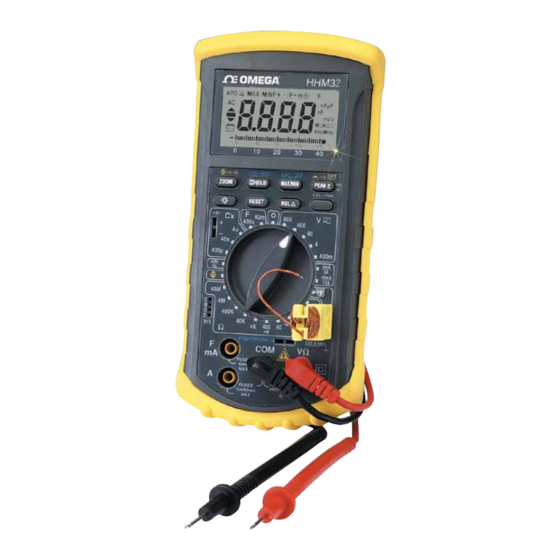
- Page 1 OMEGA...
- Page 2 European New Approach Directives. OMEGA will add the CE mark to every appropriate device upon certification. The information contained in this document is believed to be correct but OMEGA Engineering, Inc. accepts no liability for any errors it contains, and reserves the right to alter specifications without notice.
-
Page 3: Safety Information
SAFETY INFORMATION The following safety information must be observed to ensure maximum personal safety during the operation of this meter: 1. Do not use the meter if the meter or test leads look damaged, or if you suspect that the meter is not operating properly. 2. -
Page 4: Specifications
SPECIFICATIONS Display: 3¾ digit liquid crystal display (LCD) with a maximum reading of 3999. Polarity: Automatic, positive implied, negative polarity indication. Overrange: (OL) or (-OL) is displayed. Zero: Automatic. Low battery indication: the " " is displayed when the battery voltage drops below the operating level. - Page 5 DC VOLTS Ranges: 400mV,4V,40V,400V,600V Resolution: 100µV Accuracy: ±(0.25%rdg + 1dgt) Input impedance: 10MW Overload protection: 500VDC or AC rms on 400mV range 1000VDC or 750VAC rms on all other ranges AC VOLTS (50Hz - 500Hz) Ranges: 400mV,4V,40V,400V,600V Resolution: 100µV Accuracy: ±(0.75%rdg + 4dgts) on 400mV,40V,400V ranges ±(1.2%rdg + 4dgts) on 600V range ±(1.5%rdg + 4dgts) on 4V range (100Hz to 500Hz) Input impedance: 10MW...
- Page 6 AC CURRENT (50Hz - 500Hz) Ranges: 4mA,40mA,4A,10A Accuracy: ±(1.2%rdg + 4dgts) on 40mA ranges ±(3.0%rdg + 20dgts) on 4mA,4A ranges ±(3.5%rdg + 4dgts) on 10A ranges Input protection: 100mA / 250V fast blow fuse 10A / 600V fast blow ceramic fuse RESISTANCE Ranges: 40W ,400W ,4KW ,40KW ,400KW,4MW ,40MW Accuracy: ±(2.0%rdg + 10dgts) on 40W range...
- Page 7 CAPACITANCE Ranges: 400pF,40nF,4µF,400µF,40mF Accuracy: ±(2.0% rdg + 5dgts) on 400pF to 4µF ranges ±(5.0% rdg + 10dgts) on 400µF range ±(5.0% rdg + 50dgts) on 40mF range FREQUENCY (Autoranging) Ranges: Auto-ranging up to 40MHz Accuracy: ±(0.05%rdg + 3dgts) on all ranges Sensitivity: 1.0Vrms min Overload protection: 500VDC or AC rms LOGIC TEST...
-
Page 8: Operation
OPERATION Before taking any measurements, read the Safety Information Section. Always examine the instrument for damage, contamination (excessive dirt, grease, etc.) and defects. Examine the test leads for cracked or frayed insulation. If any abnormal conditions exist do not attempt to make any measurements. - Page 9 LCD Segment Check Press HOLD button while turning the meter on, and all LCD segment will be keep turn on until releasing HOLD button. Hold Feature Pressing the HOLD key to enter the Data Hold mode, the"HOLD" annunciator is displayed. When HOLD mode is selected, the meter held the present readings and stops all further measurements.
- Page 10 PEAK ± Hold Feature Pressing PEAK ± key to enter the PEAK ± hold mode, Push PEAK ± key to cycle through the peak+/ peak- readings. To prevent accidental loss of PEAK ± data, In this mode can only be cancelled by pressing and hold down the PEAK ±...
- Page 11 REL relative Button Pressing REL key to enter the Relative mode and the "D" annunciator is displayed, then store the displayed Reading as a reference value.Pressing REL key again the "D D D D D " annunciator will be blinking, LCD reads reference value. Pressing and holding down the REL key for 1 seconds to exit REL mode.
- Page 12 Voltage Measurements 1. Connect the red test lead to the "VW " jack and the black test lead to the "COM" jack. 2. Set the Function/Range switch to the desired voltage type (AC or DC) and range. If magnitude of voltage is not known, set switch to the highest range and reduce until a satisfactory reading is obtained.
- Page 13 Resistance and Continuity Measurements 1. Set the Function/Range switch to the desired resistance range or continuity position. 2. Remove power from the equipment under test. 3. Connect the red test lead to the "VW " jack and the black test lead to the "COM"...
- Page 14 Diode Tests 1. Connect the red test lead to the "VW " jack and the black test lead to the "COM" jack. 2. Set the Function/Range switch to the " " position. 3. Turn off power to the circuit under test. 4.
- Page 15 Frequency Measurements 1. Set the Function/Range switch to the Hz position. 2. Connect the red test lead to the "VW " jack and the black test lead to the "COM" jack. 3. Connect the test leads to the point of measurement and read the frequency from the display.
- Page 16 Temperature Measurements WARNING Remove test leads being measured. 1.Set the Function/Range switch to the "°F" position. 2.Connect a type k thermocouple to the jack on the instrument. Place the probe or thermocouple tip on or in the material to be measured and take the temperature reading directly from the display.
-
Page 17: Maintenance
MAINTENANCE WARNING Remove test leads before changing battery or fuse or performing any servicing. Battery Replacement Power is supplied by a 9 volt "transistor" battery. (NEDA 1604 IEC 6F22). The " " appears on the LCD display when replacement is needed. To replace the battery, remove the two screws from the back of the meter and lift off the battery case. - Page 18 CONDITIONS: Equipment sold by OMEGA is not intended to be used, nor shall it be used: (1) as a "Basic Component" under 10 CFR 21 (NRC), used in or with any nuclear installation or activity; or (2) in medical applications or used on humans. Should any...
-
Page 19: Data Acquisition
Where Do I Find Everything I Need for Process Measurement and Control? OMEGA...Of Course! TEMPERATURE DATA ACQUISITION PRESSURE/STRAIN AND FORCE HEATERS FLOW/LEVEL ENVIRONMENTAL MONITORING AND CONTROL pH/CONDUCTIVITY M-3202/0799...
Need help?
Do you have a question about the HHM32 and is the answer not in the manual?
Questions and answers