Table of Contents
Advertisement
Advertisement
Table of Contents

Related Manuals for Hyundai HY1000SI


Summary of Contents for Hyundai HY1000SI
- Page 3 Licensed by Hyundai Corporation, Korea...
- Page 4 PREFACE Thank you for purchasing a Hyundai Portable Generator. Please register your product in order for us to ensure your continuous satisfaction with our product. This manual covers the safety, operation and maintenance proce- dures for the HY1000SI and HY2000SI models.
-
Page 5: Table Of Contents
TABLE OF CONTENTS 1. Safety Precautions 1.1: Safety labels........... 1.2: Operations Safety........... 1.3: AC safety guidelines........1.4: Maintenance safety......... 1.5: Other safety hazards........2. Identification of Components.......... 3. Pre-Operation Inspection..........4. Operation 4.1: Starting the generator set....... 4.2: Using the generator set........4.3: Stopping the generator set...... -
Page 6: Safety Precautions
1. SAFETY PRECAUTIONS 1.1: SAFETY LABELS DANGER This symbol warns of hazards which can result in severe or lethal personal injury. WARNING This symbol refers to a hazardous or unsafe practice which has the potential to result in personal injury or product property damage. -
Page 7: Ac Safety Guidelines
rettes, open flames, smoke and/or sparks. • Connections for standby power to a building’s electrical system must be done by a qualified electrician and must comply with all applicable laws and electrical codes. Im- proper connections may cause serious injuries to electrical workers during power outage, and when the utility power is restored, the generator may explode or cause fires. -
Page 8: Other Safety Hazards
gasoline because explosion may occur. • Turn off the generator set before performing any mainte- nance. Otherwise it can cause severe personal injury or death • Allow the generator set to cool down before performing any maintenance. • Always wear safety glasses when cleaning the generator set with air. -
Page 9: Identification Of Components
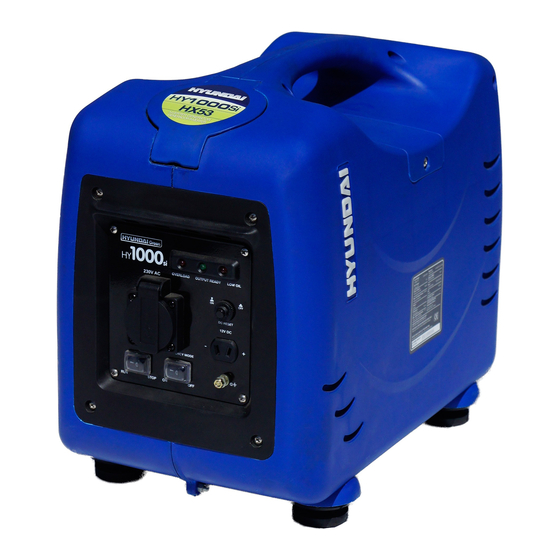
2. IDENTIFICATION OF COMPONENTS For HY1000Si Cover of fuel cap Top maintenance cover Control Panel Fuel Switch Choke Rocker Rear Cover Maintenance Cover Starter Grip... - Page 10 For HY2000Si Cover of fuel cap Top maintenance cover Control Panel Starter Grip Choke Rocker Rear Cover Primer Bulb Maintenance cover Fuel Switch...
- Page 11 Control Panel for HY1000Si Low oil indicator Overload indicator Output indicator DC breaker AC socket Grounding Start switch ECON switch DC socket AC Circuit Protector Control Panel for HY2000Si: Overload Low oil indicator Output indicator indicator AC Circuit Protector AC socket...
- Page 12 Label Placement For HY1000Si FUEL CARBURANT...
- Page 13 Label Placement For HY2000Si FUEL CARBURANT...
-
Page 14: Pre-Operation Inspection
1. Loosen the cover screws and remove the maintenance cover (Refer to Fig. 3.0 for HY1000Si and Fig. 3.1 for HY2000Si) 2. Remove the oil filler cap and wipe the dipstick clean (Refer to Fig. 3.2 for HY1000Si or HY2000Si) - Page 15 Cover Screw Maintenance Cover Fig. 3.1 Upper limit Dipstick Oil Filler Cap Fig. 3.2 Lower limit NOTICE The Oil Alert System will automatically shut off the engine before the oil level falls below the safe limit. However, to avoid the incon- venience of an unexpected shutdown, it is still advisable to visually inspect the oil level regularly.
- Page 16 spilling fuel. Do not fill above the upper limit mark (Refer to Fig. 3.3) CAUTION -Gasoline is highly flammable and explosive. Keep the engine away from heat, spark and open flame -Refuel in a well-ventilated area with the engine stopped -Handle fuel only outdoors -Wipe up spills immediately -Avoid getting dirt, dust or water in the fuel tank...
-
Page 17: Operation
Check the air filter: WARNING Never run the engine without the air filter. Rapid engine wear will result from contaminants, such as dust and dirt, being drawn through the carburetor, into the engine. 1. Loosen the cover screws, nuts and remove the maintenance cover. - Page 18 1. Rotate the fuel switch to the ON position according to the ar- row direction. (Refer to Fig. 4.0 for HY1000Si and Fig. 4.1 for HY2000Si) Turn the fuel switch to ON (counterclockwise) Fig 4.0 Fig. 4.1 2. If the engine is cold, move the choke rocker to the CLOSE posi- tion.
- Page 19 Start switch Fig. 4.4 Fig. 4.5 4. Pull slightly on the starter grip until you feel resistance and then pull briskly. (Refer to Fig. 4.6 for HY1000Si and Fig. 4.7 for HY2000Si) Fig. 4.6 Fig. 4.7 5. After the engine warms up (above 50 F), slowly turn the choke rocker to the OPEN position.
-
Page 20: Using The Generator Set
WARNING -Do not allow the starter grip to snap back. Return it slowly by hand -Grasp the carrying handle firmly to prevent the generator from falling over when pulling the starting grip NOTICE -If the engine stops and will not restart, check the engine oil level before troubleshooting other areas -Make sure the ECON switch is OFF before turning on the con- nected device... - Page 21 WARNING -To prevent electrical shock from faulty appliances, the generator should be grounded -Limit operation requiring maximum power to 30 minutes -Do not exceed the current limit specified for any one receptacle -Do not connect the generator to a household circuit WARNING -Do not modify or use the generator for other purpose than it is intended for.
- Page 22 (green) will stay ON. GROUND TERMINAL Before using generator, a ground wire must be connected to the ground terminal. Before using the ground terminal, consult a qualified electrician. (Refer to 4.8 for HY1000Si and Fig. 4.9 for HY2000Si)
- Page 23 1. Turn off the switches of the device before connecting to the generator 2. Start the generator and make sure the output indicator lights (green) come on. (Refer to Fig. 4.10 for HY1000Si and Fig. 4.11 for HY2000Si) Output indicator (green)
- Page 24 (Refer to 4.12 for HY1000Si and Fig. 4.13 for HY2000Si) Overload indicator (red)
- Page 25 -The DC socket is only used for charging a 12V battery. (Refer to Fig. 4.14 for HY1000Si and Fig. 4.15 for HY2000Si) -When using the DC socket, turn the ECON switch to the OFF posi- tion. (Refer to Fig. 4.14 for HY1000Si and Fig. 4.15 for HY2000Si) DC Breaker switch ECON switch...
-
Page 26: Stopping The Generator Set
(-) battery terminal 3. Press the start switch to RUN position 4. Press the DC breaker switch to ON position (Refer to Fig. 4.12 for HY1000Si and Fig. 4.13 for HY2000Si) 5. Start the generator 4.3: STOPPING THE GENERATOR SET For HY1000Si/HY2000Si (AC Operation) 1. - Page 27 For HY1000Si/HY2000Si (DC Operation only) NOTICE An overloaded DC circuit, excessive current draw by the bat- tery, or a wiring problem will automatically trip (turn off) the DC breaker switch. If this happens, wait a few minutes before press- ing the breaker switch to the ON position to resume operation. If the breaker switch continues to go OFF, discontinue charging and contact your authorized dealer.
-
Page 28: Maintenance
NOTE: Some of these maintenance techniques can be dangerous and should be performed by a qualified technician For HY1000Si/HY2000Si: In order to maintain good performance and extend the service life of the generator, period inspection and adjustments should be done... - Page 29 Each Every 6 Every Each quar- Mainte- month months year Item using nance or 20 or 100 or 200 time or 50 hours hours hours hours Check • level gine Change • • Check • •(refer Filter Clean to no- tice 1) Check- •...
-
Page 30: Air Filter Service
5.3: Air Filter Service 1. Loosen the cover screws nuts and remove the maintenance cover 2. Remove the air filter cover 3. Remove the air filter sponge (refer to Fig. 5.0) 4. Check the filter sponge to make sure that it is clean and in good condition. -
Page 31: Changing Engine Oil
2. Loosen the cover screws and remove the maintenance cover 3. Place a container next to the engine to catch the used oil (Refer to Fig. 5.2 for HY1000Si and Fig. 5.3 for HY2000Si) 4. Remove the oil filler cap/dipstick and drain the oil into the con-... -
Page 32: Spark Plug Service
1. Remove the top screw and the top maintenance cover (Refer to Fig. 5.5 for HY1000Si and Fig. 5.6 for HY2000Si) Top maintenance cover Top maintenance cover Screw Screw Fig. 5.5 Fig. 5.6 2. Remove the ignition coil (Refer to Fig. 5.7 for HY1000Si and Fig. - Page 33 3. Clean any dirt and debris around the spark plug base 4. Use a wrench to remove the spark plug (Refer to Fig. 5.9 and Fig. 5.11 for HY1000Si, Fig. 5.10 and Fig. 5.12 for HY2000Si) Spark Plug Wrench Fig. 5.9...
- Page 34 Ignition Coil Ignition Coil DC Wire High Voltage wire High Voltage wire DC Wire Spark Plug Spark Plug Fig. 5.11 Fig. 5.12 5. Visually inspect the spark plug. Clean the spark plug with a brush if it is to be reused. 6.
-
Page 35: Transportation & Storage
Rotate the fuel switch to the ON position (Refer to Fig. 4.0 for HY1000Si and Fig. 4.1 for HY2000Si). 2. Start the generator and operate it in the idle position until all... - Page 36 Fig. 5.14 for HY1000Si and Fig. 5.15 for HY2000Si) Fig. 5.14 Fig. 5.15 3. Discharge Oil a) Press the start switch to the STOP position and make sure the fuel cap is fully closed. b) Loosen the cover screws and remove the maintenance cover...
-
Page 37: Troubleshooting
6. TROUBLESHOOTING WARNING -Many troubleshooting procedures present hazards which can result in severe personal injury or death. Only trained and experienced service personnel with knowledge of fuels, electricity, and machinery hazards should perform service procedures. Review Safety Precautions. WARNING -A hot generator can cause severe burns. Always allow the generator set to cool before performing any maintenance service. - Page 38 Start a few times to ensure fuel No fuel in the carburator Replace spark plug enters the carburator Spark plug not working Start a few times to ensure fuel No fuel in the carburator Send generator to authorized dealer If the device that connects the generator doesn’t start: enters the carburator Replace spark plug Spark plug not working...
-
Page 39: Specifications & Data
7. SPECIFICATIONS & DATA HY1000i Type Digital Inverter / Sine Wave 60Hz Frequency Rated AC Output Power (kW) Max AC Output Power (kW) Voltage 120V XG142F Model OHV, Forced-Air Cooling, single cylinder, Type 4 stroke, Gasoline engine Bore x Stroke (mm x mm) 43.5 x 36 Displacement (cc) Rated Power (kw) - Page 40 HY2000Si Type Digital Inverter / Sine Wave Frequency Rated AC Output Power (kW) Max AC Output Power (kW) 60Hz 120V Voltage (V) Model XG152F OHV, Forced-Air Cooling, single cylinder, Type 4 stroke, Gasoline engine 52 x 58 Bore x Stroke (mm x mm) Displacement (cc) 3.5/5000rpm Rated Power (kw)
-
Page 41: Wiring Diagram
8. WIRE DIAGRAMS For HY1000Si... - Page 42 For HY2000Si...
-
Page 43: Warranty
9. WARRANTY Warranty Terms and Conditions Canadian distribution of Hyundai branded Portable generators are distributed by: Midland International 26 Huddersfield Rd. Unit #2 M9W-5Z6 Canada This product is warranted to be free of defects in material and workmanship for two years from date of purchase. This warranty guarantees that any defective parts will be repaired or replaced at no cost, including diagnosis and replacement parts. - Page 44 6) Damage caused by operation with improper fuel, or at speeds, loads, conditions, or modifications contrary to published specifications. 7) Items not supplied by Hyundai, including, but not limited to; starting batteries, battery cables, external wiring, fuel lines, filters, etc;(refer to exclusions)
- Page 45 left our facility. It is the customer’s responsibility to take great care when handling a battery so no spillage of acid will occur and cause corrosion; damage caused by battery acid is not covered under this warranty. Product Registration Product registration is required for product support and warranty coverage.
-
Page 46: Glossary
10. GLOSSARY AC socket- The receptacle for the device plug used for AC applica- tion AC Circuit Protector- It protects AC circuits from being damaged due to overload or short circuit by stopping the flow of electricity between the generator and device. Air Filter- It removes dust from engine intake air. - Page 47 Output Indicator Light- The output indicator light (green) is illumi- nated when the generator is operating normally. It indicates that the generator is producing power at the receptacles Overload Indicator Light- If the generator is overloaded, or if there is a short circuit in a connected device, the overload indicator light (red) will go ON.
-
Page 48: Questionnaire
Please complete and mail the form below, or register online by visiting our website: www.Hyundaipower.ca Personal Information First name: Last name: Address: Postal code: City: Province: Product Information Model name: Serial number: Date of purchase: Questionnaire Store name and number: Purchase price: Why our generator? Power rating... - Page 49 Questionnaire How did you nd out about us Internet Print In-Store Radio/TV Store yer Word of mouth Primary usage Emergency Tools Recreational Primary location of usage Work Home Gender Female Male Martial status Single Married Date of birth...
- Page 50 Questionnaire Number of people in household other Primary residence Rent Education Full University Partial Secondary Secondary College Household income (thousand) Primary method of Online In-Store purchasing items Mail order Midland International Inc. 26 Hudders eld Rd. Please Mail to: Online registration at: Unit # 2 www.Hyundaipower.ca Etobicoke, Ontario...
-
Page 51: Notes
NOTES... - Page 52 NOTES...
- Page 53 NOTES...
- Page 54 NOTES...
- Page 55 NOTES...
Need help?
Do you have a question about the HY1000SI and is the answer not in the manual?
Questions and answers