Table of Contents

Related Manuals for Greenlee 1990


Summary of Contents for Greenlee 1990
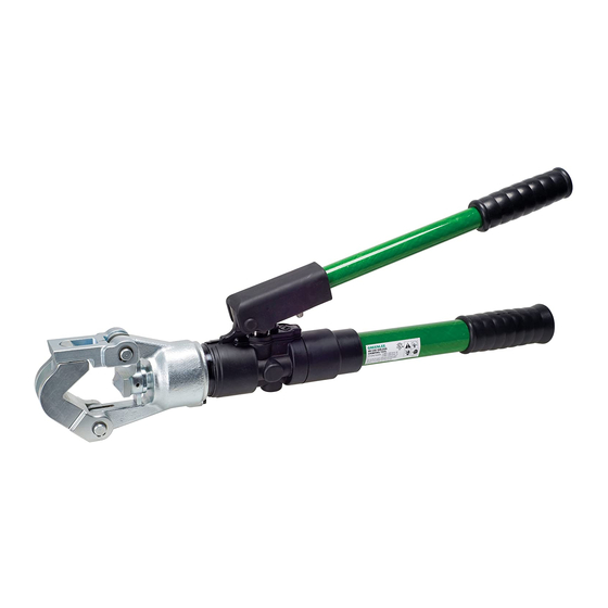
- Page 1 1990 Dieless Hydraulic Crimping Tool Serial Codes WH and YM Read and understand all of the instructions and safety information in this manual before operating or servicing this tool. 999 8517.9 © 2000 Greenlee Textron SB 226 REV 5 4/00...
-
Page 2: Table Of Contents
Description Loctite is a registered trademark of Loctite Corporation. Univis is a registered trademark of Exxon Corporation. The Greenlee 1990 Dieless Hydraulic Crimping Tool is a self-contained tool intended to crimp copper and aluminum compression connectors. A single set of Other Publications integral dies provides a wide crimping range. -
Page 3: Important Safety Information
Failure to observe this warning can or property damage. result in severe injury or death. • Do not operate the tool without dies in place. Damage to the ram or crimping head may result. Greenlee Textron / Subsidiary of Textron Inc. -
Page 4: Identification
7. The handle grips have “motorcycle style” ribs. 7. The handle grips are lobed. Note: The Greenlee 44999 is similar in appearance to these tools, with some major differences: • Serial Code is not WH or YM. • Movable die is yellow. -
Page 5: Tools And Supplies
(97) and reseal with RTV (98). Add hydraulic oil (see Air Purging and Oil Filling Procedure). • not within the ranges stated in Step 4 or Step 5, proceed to the Pressure Adjustment Procedure. Greenlee Textron / Subsidiary of Textron Inc. -
Page 6: Pressure Adjustment Procedure
6. Remove the tool from the vise and pour the oil into a waste oil container. • screw (100) 7. Clamp to tool head in the vise. Remove O-ring (21) and reservoir (20). Add oil until the pump block is 3/4 full. Greenlee Textron / Subsidiary of Textron Inc. -
Page 7: Pressure Calibration Check
• If the test slug checkpoint fits into the GO slot and does not fit into the NO GO slot, the pressure relief valve is set correctly. Greenlee Textron / Subsidiary of Textron Inc. -
Page 8: Air Purging And Oil Filling Procedure
(18). Replace the set screw (17) and tighten Set Screw securely. (17) 12. Cover the set screw with a silicone rubber sealant, ® ® ® such as Dow Corning Silastic Multipurpose Sealant. Greenlee Textron / Subsidiary of Textron Inc. -
Page 9: Die Replacement
• to increase the distance, remove a spacer (102) • to decrease the distance, add a spacer (102) 2.250" 2.250" 2.205" 2.205" 5. Install the movable die (26) and secure with the set screw (25). Greenlee Textron / Subsidiary of Textron Inc. -
Page 10: Disassembly
Note: Pull the cylinder straight off of the cap to (38), spring (39), guide (35) and wiper (34). prevent damaging the driving rod. 9. Replace all available packing (O-rings, backup rings, springs, balls, wiper, etc.). Greenlee Textron / Subsidiary of Textron Inc. - Page 11 3. Slide out the relief valve cap (87) and remove the following parts: stepped rod (84), roller guide (83), adjusting roller (88), two slides (89), valve spring cap (86), valve spring (85) and relief valve plunger (81). Greenlee Textron / Subsidiary of Textron Inc.
-
Page 12: Assembly
2. Assemble copper washer (67) and high-pressure plunger (68) to the pump block. Torque to 24.5 to 27 Newton-meters (18 to 20 foot-pounds). 3. Install low-pressure plunger assembly onto the high- pressure plunger assembly. Greenlee Textron / Subsidiary of Textron Inc. - Page 13 9. Install the relief valve cover (90) and adjust it so that the stepped rod moves freely. Secure the cover with two machine screws (91). Serial Code YM: Install set screw (93) and secure it with jam nut (92). Flat Side Greenlee Textron / Subsidiary of Textron Inc.
- Page 14 7. Install the spacer(s) (102) and movable die (26). Secure by tightening set screw (25). 8. Fasten the fixed die to cylinder with pins (23, 24). Secure pin (24) with retaining rings (27). Greenlee Textron / Subsidiary of Textron Inc.
-
Page 15: Service Tips
Add oil until reser- the front pin and pivoting the handle up and beyond voir overflows. Wipe off the excess oil. the normal stroke. 6. Proceed to calibrate the tool. See the Pressure Adjustment Procedure. Greenlee Textron / Subsidiary of Textron Inc. -
Page 16: Retrofit Kits
Repair kit includes grip and handle (1, 18). assembly (with grip) The grips are not interchangeable. When replacing either handle assembly, you might consider replacing both of them so that two grips are similar in appearance. Greenlee Textron / Subsidiary of Textron Inc. -
Page 17: Troubleshooting
C. Damaged O-ring on low pressure plunger C. Replace O-ring and backup ring. D. Damaged reservoir D. Replace reservoir. E. Damaged or missing O-ring on reservoir E. Replace O-ring. F. Reservoir is underfilled F. Fill reservoir and purge air. Greenlee Textron / Subsidiary of Textron Inc. -
Page 18: Illustrations And Parts Lists
1990 Dieless Hydraulic Crimping Tool Illustration — Serial Code WH 101 RTV 98 RTV 17 16 RTV Greenlee Textron / Subsidiary of Textron Inc. - Page 19 1990 Dieless Hydraulic Crimping Tool 30 (outer) 30 (inner) 30 (inner) 30 (outer) Greenlee Textron / Subsidiary of Textron Inc.
- Page 20 O-ring, .334 x .475 x .070" ................1 50394 905 0394.5 O-ring, .750 x 1.00 x .125"–70D Nitrile ............1 51272 905 1272.3 Backup Ring, Spiral, .750 x .992 x .027" ............ 1 Greenlee Textron / Subsidiary of Textron Inc.
- Page 21 Pump Block Repair/Retrofit Kit (Required) Replace worn or broken components with identical WH-style components: 33013 503 3013.6 Hydraulic Repair Kit 33015 503 3015.2 Die Replacement Kit (includes two inner dies and two outer dies) Greenlee Textron / Subsidiary of Textron Inc.
- Page 22 1990 Dieless Hydraulic Crimping Tool Illustration — Serial Code YM Glue grip (11) to handle (5). 101 RTV 98 RTV 16 RTV Greenlee Textron / Subsidiary of Textron Inc.
- Page 23 1990 Dieless Hydraulic Crimping Tool Greenlee Textron / Subsidiary of Textron Inc.
- Page 24 Screw, Cap, 1/4-20 x 1.00" Socket Head........... 4 32535 503 2535.3 Washer, Flat, .260 x .390 x .046" Copper ........... 4 50883 905 0883.1 Backup Ring, Spiral, .375 x .485 x .027" Teflon ......... 1 Greenlee Textron / Subsidiary of Textron Inc.
- Page 25 Cylinder and Die Head Repair Kit 36150 503 6150.3 Valve Cap and Cover Repair Kit 36151 503 6151.1 Reservoir Handle Repair Kit 36152 503 6152.0 Pump Handle Repair Kit 36153 503 6153.8 Pump Block Repair Kit Greenlee Textron / Subsidiary of Textron Inc.
- Page 26 Greenlee Textron / Subsidiary of Textron Inc. 4455 Boeing Drive, Rockford, IL 61109-2988 USA Customer Service (International): 815/397-7070 • Fax: 815/397-9247 Customer Service (North America): 800/435-0786 • Fax: 800/451-2632, 815/397-1865 Canada Fax: 800/524-2853 Printed in the U.S.A.
Need help?
Do you have a question about the 1990 and is the answer not in the manual?
Questions and answers