enphase Envoy Communications Gateway Installation And Operation Manual
Envoy communications gateway
Hide thumbs
Also See for Envoy Communications Gateway:
- Installation and operation manual (100 pages) ,
- Quick install manual (4 pages) ,
- Quick install manual (4 pages)

Related Manuals for enphase Envoy Communications Gateway


Summary of Contents for enphase Envoy Communications Gateway
- Page 1 I NS TA L L A TI O N A N D O P E R A TI O N MA NU A L Envoy Communications Gateway 141-00011, Rev 05...
-
Page 2: Contact Information
Product information is subject to change without notice. All trademarks are recognized as the property of their respective owners. For warranty text refer to http://www.enphase.com/warranty. User documentation is updated frequently; Check the Enphase website (http://www.enphase.com/support) for the latest information. Copyright © 2013 Enphase Energy Inc. All rights reserved. -
Page 3: Table Of Contents
Safety Instructions ..........................5 Audience ............................5 The Enphase Envoy Communications Gateway ................. 6 Other Elements in the Enphase System ..................7 How the Envoy Communications Gateway Works ................7 Envoy Installation ........................8 Planning and Preparation ........................ 8 System Sizing..........................8 Preinstallation Checks ........................ - Page 4 Clear DC Resistance-Low Condition ..................46 Set Up Device Scan Control ...................... 48 ZigBee Device Configuration ..................... 50 Set the Time Zone (optional) ...................... 50 Other Administration Tasks ......................50 Event Messages ..........................51 Technical Data ..........................59 2013 Enphase Energy Inc. 141-00011 Rev 05...
-
Page 5: Important Information
National Electrical Code (NEC), ANSI/NFPA 70. Do not attempt to repair the Envoy; it contains no user-serviceable parts. Tampering with or opening the Envoy will void the warranty. If the Envoy fails, contact Enphase Customer Support for assistance (support@enphaseenergy.com). ... -
Page 6: The Enphase Envoy Communications Gateway
Envoy Installation and Operation The Enphase Envoy Communications Gateway The Envoy® Communications Gateway is an integral component of the Enphase® Microinverter System™. It operates between the Enphase Microinverters and the Enphase Enlighten® web-based monitoring and analysis software. The Envoy functions as a gateway and monitors the microinverters that are connected to the PV modules. -
Page 7: Other Elements In The Enphase System
Envoy Installation and Operation Other Elements in the Enphase System The Enphase Microinverter converts the DC output of the PV module into grid-compliant AC power. In addition to performing the DC to AC conversion, it maximizes the PV modules’ energy production by using a sophisticated Maximum Power Point Tracking (MPPT) algorithm. -
Page 8: Envoy Installation
Review the following preinstallation checks and sizing considerations before you install the Envoy. System Sizing The Envoy is capable of servicing a large system of Enphase Microinverters. This number varies with Envoy model. Check the model number (SKU) on the Envoy box, or on the back of the Envoy, to determine which model you are installing. -
Page 9: Installation Flow
Envoy Installation and Operation Installation Flow 2013 Enphase Energy Inc. 141-00011 Rev 05... -
Page 10: Install The Envoy
You can build the system map manually, by peeling the serial number label from the Envoy and placing the label on the installation map, or you can use the ArrayGun feature from the Enphase Installer Toolkit to easily build and configure a system. Refer to http://enphase.com/products/arraygun/... -
Page 11: Register The Envoy
Envoy Interface to check or set the Grid Profile, see “Change or View the Grid Profile” on page 38. Click Save to submit the form. You will receive a confirmation message: “Activation Created Successfully.” 2013 Enphase Energy Inc. 141-00011 Rev 05... -
Page 12: Find A Location For The Envoy
Envoy Installation and Operation 3. Find a Location for the Envoy Enphase recommends that you place the Envoy as close to the load center as possible. This ensures that the Envoy receives the strongest possible communications signal from each microinverter. Place the Envoy indoors or in an environmentally protected location. -
Page 13: Connect Power Line Communication Bridges (If Required)
0kWh (see definitions of W and kWh on 0kWh page 19) until the microinverters are discovered and microinverter monitoring begins. Power production also shows 0W and 0kWh for about a minute whenever the Envoy powers up. 2013 Enphase Energy Inc. 141-00011 Rev 05... -
Page 14: Install The Modules And Microinverters
Home screen until the device scan is complete. NOTE: For sites with neighboring Enphase systems, do not allow a device scan to run overnight because it may discover neighboring microinverters when they first power-up in the morning. -
Page 15: Wall Mount The Envoy (Optional)
You will need two #8 screws (4.17 mm or 0.16 in. diameter); maximum screw head diameter is 8.9mm (0.35 in.). b. Slide the Envoy onto the mounting screws, aligning the Envoy screw holes with the screws as shown. 2013 Enphase Energy Inc. 141-00011 Rev 05... -
Page 16: Build The Virtual Array
Enlighten from the installation map you created. You can scan and upload the paper copy of the Installation Map, or you can use the ArrayGun feature from the Enphase Installer Toolkit to easily build and configure a system. Refer to http://enphase.com/products/arraygun/ for more information. -
Page 17: Envoy Operation
WARNING: Stop the scan once all of the devices are detected (see page 14). For sites with neighboring Enphase systems, do not allow the device scan to run overnight because it may discover neighboring microinverters when they first power-up in the morning. -
Page 18: Lcd Screen Display At Initial Start Up
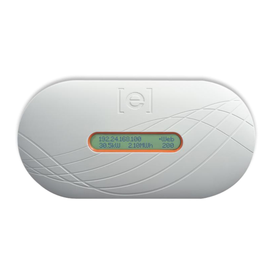
IP address and the “+Web” status indication in the LCD screen. The normal, post- 192.168.2.140 +Web installation boot sequence is similar to the initial start up, although the “Initializing Data” screen is not repeated. Level: [ Devices: 2013 Enphase Energy Inc. 141-00011 Rev 05... -
Page 19: Normal Operation
1. Press and hold this button. After two Menu seconds the Envoy Button menu appears in the Envoy’s LCD screen. 2. Continue holding the Menu button. Menu items appear in the following order: 2013 Enphase Energy Inc. 141-00011 Rev 05... -
Page 20: Exit Menu
Device Scan Disable Device Scan Enable Communication Check Disable Communication Check View Grid Configuration Get New IP Address Enable Connection To Enphase Disable Connection To Enphase View Serial Number Select New Locale 2013 Enphase Energy Inc. 141-00011 Rev 05... -
Page 21: Initiating A Scan For New Microinverters
If you add additional microinverters to an existing system or replace a microinverter, you must run a scan to detect the new devices. To initiate a scan after you add new microinverters to an existing Enphase system, perform the following steps. Alternatively, you can initiate a scan through the Administration page when connected to the Envoy local interface with a computer or via Enlighten (refer to “Using Enlighten to... - Page 22 4. After 20 minutes, the communications check stops. To stop the communications check before it times out, press and hold the menu button to activate the Envoy menu. When “Disable Communication Check” is displayed, release the menu button. 2013 Enphase Energy Inc. 141-00011 Rev 05...
-
Page 23: Viewing The Grid Configuration
Number of microinverters that cannot be set with a grid profile. (n)devices are set Number of microinverters that are set with (local spec) with a grid profile and the name of the specification being used. 2013 Enphase Energy Inc. 141-00011 Rev 05... -
Page 24: Getting A New Ip Address
Menu button. Get New IP Address The LCD screen now reads: Getting IP Address Once the new IP address has been requested, the LCD will return to the default display. 2013 Enphase Energy Inc. 141-00011 Rev 05... -
Page 25: Enabling A Connection To Enphase
Envoy Installation and Operation Enabling a Connection to Enphase The Enable Connection to Enphase menu item creates a secure connection to Enphase allowing Enphase personnel to troubleshoot the system remotely. To open a connection to Enphase: 1. Press and hold the Envoy Menu button. After two seconds the Envoy menu appears. -
Page 26: Viewing The Envoy Serial Number
3. The Envoy LCD panel will scroll through the available locale settings. When you see the setting you need, press the Menu button and hold for two seconds. English Français Deutsch Italiano Español 2013 Enphase Energy Inc. 141-00011 Rev 05... -
Page 27: How The Envoy Works With Enlighten
You can then use Array Builder, a tool available to installers, to build the virtual array. Use the installation map you created during installation as a reference during this task. Or you can use the ArrayGun feature from the Enphase Installer Toolkit to easily build and configure a system. Refer to http://enphase.com/products/arraygun/... -
Page 28: Troubleshooting
Troubleshooting an Enphase Installation at http://www.enphase.com/support. WARNING: Do not attempt to repair the Enphase Envoy; it contains no user-serviceable parts. If it fails, contact Enphase customer service to obtain an RMA (return merchandise authorization) number and start the replacement process. -
Page 29: Issue: Envoy Displays Zero Bars
Add a subpanel with a small subset of circuit breakers. In this case, it is best to add an additional 5-Amp circuit breaker and then run an outlet off that subpanel. Plug the Envoy into that AC outlet, so that it can be close to the PV circuit breaker. 2013 Enphase Energy Inc. 141-00011 Rev 05... -
Page 30: Network Basics And Troubleshooting
Enphase offers technical support at support@enphaseenergy.com for Envoy issues, but Enphase's Support responsibility does not extend to the premises network or LAN. Issue: IP Address Problems When the Envoy first boots up, it is configured to perform a DHCP broadcast, requesting an IP address from a DHCP source. -
Page 31: Issue: Lcd Screen Displays "Scanning Inhibited
Issue: LCD Screen Displays "Scanning Inhibited" This message displays after an installer has used the Installer's Toolkit to provision the Envoy. Leave the Envoy in this condition for normal operation. If you need to re-enable scanning, contact Enphase Customer Support (support@enphaseenergy.com). -
Page 32: Dhcp Versus Static Ip Addressing
If outbound firewall rules are applied at the site, you must configure a static IP address for the Envoy and add new rules that allow outbound access as follows: Direction Source Protocol Port Destination <Envoy IP address> reports.enphaseenergy.com <Envoy IP address> securereports.enphaseenergy.com <Envoy IP address> home.enphaseenergy.com <Envoy IP address> us.pool.ntp.org 2013 Enphase Energy Inc. 141-00011 Rev 05... -
Page 33: Replacing An Envoy
The Envoy connects to these servers using their DNS names. If you add firewall rules for Envoy reporting, Enphase recommends using the DNS names rather than the underlying IP addresses. This is because the IP addresses are subject to change without notice. -
Page 34: Envoy Local Interface
Envoy Installation and Operation Envoy Local Interface The Envoy relays data to Enlighten, and connection to the Enphase Enlighten web-based monitoring and analysis software requires an Internet connection. However, if there is no broadband router at the installation site, you can communicate directly with the Envoy using the Ethernet port and a personal computer with a web browser. -
Page 35: Home Screen
Events Screen To view system events for your system, click Events from the Envoy home screen to navigate to the Events screen. This screen includes information on events occurring on connected Enphase devices. 2013 Enphase Energy Inc. 141-00011 Rev 05... -
Page 36: Production Screen
To view system energy harvest statistics for your system, click Production from the Envoy home screen to navigate to the production screen. Inventory Screen To view a listing of the devices in your system, click Inventory from any screen to navigate to the inventory screen. 2013 Enphase Energy Inc. 141-00011 Rev 05... -
Page 37: Administration Screen
The Administration screen of the Envoy local interface contains several configurable options. Click Administration to access this menu. NOTE: For Envoy performance reasons, Enphase does not recommend giving the Envoy a publicly accessible IP address. However, if you must place the Envoy on a public-facing IP address, Enphase recommends that you change the Administration password to disallow unauthorized modification to your Envoy. -
Page 38: Change Or View The Grid Profile
Envoy Installation and Operation Change or View the Grid Profile Many Enphase Microinverters have field-adjustable voltage and frequency trip points. Trip points are input voltage or frequency values that trigger the microinverters to shut down when the values are exceeded. If the local utility requires adjustments to these trip points, you can set up the system to use an alternate Grid Profile (set of trip points). - Page 39 Configuration screen appears, which indicates that the microinverters are using the factory- installed grid profile. This screen allows a licensed solar professional to select and apply the appropriate trip points for the solar installation. 2013 Enphase Energy Inc. 141-00011 Rev 05...
- Page 40 8. Once logged in at the Enlighten website, locate the Grid Profile Change Token widget. If you don’t see this widget add it now: Click Add a widget. Select Grid Profile Change Token. 2013 Enphase Energy Inc. 141-00011 Rev 05...
- Page 41 Copy this token. 11. Click Get Token. 12. Copy the token. 13. Paste or enter the token in the Grid Profile screen. 14. Click Apply Grid Profile. This propagates the settings to the microinverters. 2013 Enphase Energy Inc. 141-00011 Rev 05...
- Page 42 This screen also allows you to generate a report to confirm that the microinverters have been set with an updated grid profile. 15. Click View Device Profile Report. The Device Profile Report screen appears. 16. Enter the site information in the window provided. 2013 Enphase Energy Inc. 141-00011 Rev 05...
- Page 43 17. Use your browser to send this report to your printer or to save it to a file. After printing or saving the file, you can send it to the local regulatory agency to verify the trip point settings. The report will look like the following example. 2013 Enphase Energy Inc. 141-00011 Rev 05...
- Page 44 Envoy Installation and Operation 2013 Enphase Energy Inc. 141-00011 Rev 05...
-
Page 45: Clear Gfi Tripped Condition
If a microinverter registers a GFI Tripped condition, you can attempt to clear this condition through the Envoy Interface. An Envoy is required to send the clear-gfi message to clear the condition. If the condition does not clear after you perform the following procedure, contact Enphase Energy customer support at support@enphaseenergy.com. -
Page 46: Clear Dc Resistance-Low Condition
If a microinverter registers a DC Resistance Low condition, you can attempt to clear this condition through the Envoy Interface. An Envoy is required to send the clear-dc-resistance-low message to clear the condition. If the condition does not clear after you perform the following procedure, contact Enphase Energy customer support at support@enphaseenergy.com. - Page 47 2. Click on the serial number of the unit showing the DC Resistance Low - Power Off condition. The Control Flags screen appears. CAUTION: The other control flags (reboot and cmd-alert) on this screen should be used only when recommended by Enphase. Their functions are: reboot - reboots the inverter ...
-
Page 48: Set Up Device Scan Control
This initial scan is the only scan needed for most systems. NOTE: At sites with more than 100 microinverters, Enphase recommends using a controlled device scan and specifying the total number of devices to be discovered. This speeds up the discovery process. - Page 49 5. Click Start Scan to complete this task. The LCD screen displays the following, where “nnnn” represents the number of microinverters (devices) detected. Priority Scan is Active. Devs: nnnn 2013 Enphase Energy Inc. 141-00011 Rev 05...
-
Page 50: Zigbee Device Configuration
Envoy Installation and Operation ZigBee Device Configuration Use the ZigBee Device Configuration menu option only if you are also installing an Enphase compatible GE i210+ Revenue Grade Meter (RGM). For complete installation instructions, refer to the Metering and Management Solution Installation and Operation Manual at http://www.enphase.com/support. -
Page 51: Event Messages
10 minutes was too high for the configured grid profile. If the condition persists: Contact your installer or refer to the Troubleshooting Guide at http://www.enphase.com/support. 2013 Enphase Energy Inc. 141-00011 Rev 05... - Page 52 Recommended Action: No action is required. Description: The Envoy has received a control request made via the Envoy interface (Administration > Device Conditions and Controls page) or via Enlighten. This uncommon condition will occur only during isolated troubleshooting procedures by Enphase personnel. Critical Critical Recommended Action: This condition should correct itself.
- Page 53 46. The insulation Low Power Off resistance (IR) sensor can be reset via the Enphase Envoy's Device Conditions and Controls page, or Enlighten’s Current Issues page. Note that the condition will not clear after sensor reset if the failure is still present.
- Page 54 If the condition persists: If the GFI event persists after clearing the condition from the Envoy, contact your installer or refer to the Troubleshooting Guide at http://www.enphase.com/support For further assistance, contact Enphase Energy customer support at support@enphase.com. 2013 Enphase Energy Inc. 141-00011 Rev 05...
- Page 55 Envoy has discovered all microinverters, contact Enphase Energy customer support. Note that the Envoy requires a minimum of 3 bars to communicate effectively with the microinverters for the software upgrade.
- Page 56 D380 Microinverter. The message indicates that the Envoy detects a communications problem with the indicated D380(s). If the condition persists: Contact Enphase Customer Support at support@enphseenergy.com for a software upgrade. If the D380 does not respond to the upgrade, it will need to be replaced.
- Page 57 Envoy, remove those devices from the outlet to improve signal strength. If the Enphase Envoy was recently relocated or if new devices or appliances were added to the circuit, it is possible that the new situation is not suitable for power line communication.
- Page 58 Description: The microinverter is too hot and is not producing Temperature power. This very rare condition usually clears without intervention. Recommended Action: No action is required unless the condition persists. If it persists, contact Enphase Energy customer support. Power Power generation...
-
Page 59: Technical Data
CAN ICES-3 (B)/NMB-3(B) Meter accuracy Envoy metering is qualified as +/- 5% or better. The Envoy is included in the List of Eligible System CSI Eligibility Performance Meters for the CSI program. 2013 Enphase Energy Inc. 141-00011 Rev 05...
Need help?
Do you have a question about the Envoy Communications Gateway and is the answer not in the manual?
Questions and answers