Table of Contents
Advertisement
Advertisement
Table of Contents

Subscribe to Our Youtube Channel
Related Manuals for Jet HBS-1321W WMH


Summary of Contents for Jet HBS-1321W WMH
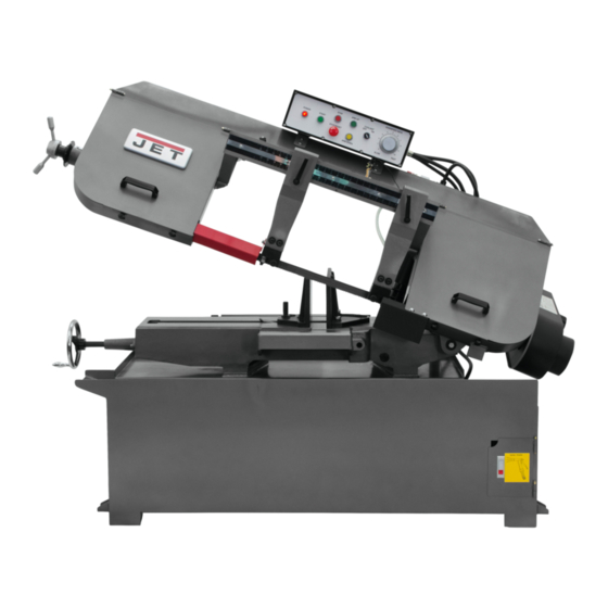
- Page 1 This Manual is Bookmarked Operating Instructions and Parts Manual Semi-Automatic Bandsaw Model HBS-1321W WMH TOOL GROUP 2420 Vantage Drive Elgin, Illinois 60123 Part No. M-414471 Ph.: 800-274-6848 Revision G 7/05 www.wmhtoolgroup.com Copyright © WMH Tool Group...
-
Page 2: Warranty And Service
Warranty and Service WMH Tool Group warrants every product it sells. If one of our tools needs service or repair, one of our Authorized Service Center located throughout the United States can provide quick service or information. In most cases, a WMH Tool Group Service Center can assist in authorizing repair work, obtaining parts, or perform routine or major maintenance repair on your JET product. -
Page 3: Warnings
• Read and understand the entire instruction manual before attempting assembly or operation. • All JET bandsaws are designed and intended for use by properly trained and experienced personnel only. If you are not familiar with the proper and safe operation of a bandsaw, do not use until proper training and knowledge have been obtained. -
Page 4: Table Of Contents
Specifications: Model: Stock Number...414471 Capacity: Round at 90° (in) ... 13 Round at 45° (in) ... 13 Rectangle at 90° (in) ... 13 x 16-1/2 ...7 x 21 Rectangle at 45° (in) ... 13 x 15-1/2 Throat Depth (in)... 13 Blade Size (in) ... -
Page 5: Uncrating And Cleanup
Uncrating and Cleanup Read and understand the entire manual before attempting setup or operation. Finish uncrating the saw and inspect for damage. If any damage has occurred, contact your local distributor. Remove all bolts attaching machine to shipping base. Leave packing material between vice clamps and saw head intact until bandsaw has been lifted to its final position. -
Page 6: Electrical Connections
3Ph. and is prewired 230 volt from the factory. Confirm power source available at the saw's location is the same as the saw is wired. To switch the HBS-1321W from 230V to 460V, the following items will have to be changed: Bandsaw must always be properly grounded. -
Page 7: Prior To Operation
6. Select proper speed and feed rate for material being cut. See speed selection chart found in the enclosed "Guide to Bandsawing" booklet supplied with this saw. 7. Material to be cut must be securely held in the vise. See vise adjustment page 8. -
Page 8: Adjusting Vise Square To Blade
WARNING Disconnect machine from the power source before adjusting or changing vise position! Failure to comply may cause serious injury! Adjusting Vise Square to the Blade Position A 1. Place a machinist's square on the bed against the blade and the vise. The square should lie along the entire length of the vise and blade without a gap. -
Page 9: Changing Blade Speeds
Rate of feed is important to bandsaw performance; excessive pressure may break the blade or stall the saw. Insufficient pressure rapidly dulls the blade. Material chips or shavings are the best indicator of proper speed and downfeed. The ideal chip is thin, tightly curled, and warm to the touch. -
Page 10: Changing Blades
Failure to comply may result in serious injury! 1. Raise the saw arm approximately 6". 2. Disconnect machine from power source. 3. Open both wheel covers and clean chips out of both wheel housings. Loosen lock knobs and remove upper and lower blade guards. -
Page 11: Guide Roller Adjustment
Guide Roller Adjustment The bearings come pre-adjusted from the factory. If adjustment is needed follow the below steps: 1. Disconnect machine from the power source. 2. Loosen two hex socket cap screws (A, Fig. 9). 3. Move guide seat (B, Fig. 9) up or down until an approximate clearance of .003"... -
Page 12: Blade Tracking Adjustment
Use extreme caution so as not to come into contact with the blade! 1. Raise saw arm to its highest position. 2. Locate tracking adjustment plate on the backside of the idle wheel. 3. Loosen the three bolts (A, Fig. 12) located on the top of the tracking nuts. -
Page 13: Round At 90° (In)
To change gear box lubricant: Disconnect machine from the power source. Remove drain plug and allow lubricant to drain completely. The drain plug is located on lower front of gear case under right wheel cover. Remove drain plug with a hex wrench. -
Page 14: Bed And Base Assembly Breakdown & Parts List
Bed and Base Assembly... - Page 15 Parts List for the JET HBS-1321W Bandsaw Index Part 1...1321W-01 ...Base ..1 2...TS-1492061 ...Hex Cap Bolt...M12x65... 4 3...TS-1540081 ...Hex Nut...M12... 4 4...1321W-04 ...Coolant Pump ...1/6HP... 1 4-1...1321W-04-1 ...Cross Point Screw...M6x16... 2 4-2...1321W-04-2 ...Spring Washer ...M6 ... 2 4-3...1321W-04-3 ...Flat Washer...M6 ... 2 5...TS-1524041 ...Set Screw ...M8x16...
- Page 16 21 ...1321W-21 ...Handle Wheel Assembly ..1 21-1...TS-0270031 ...Set Screw ...5/16"x3/8"... 2 21-2...1321W-21-2 ...Handle ..1 22 ...1321W-22 ...Rack ..1 23 ...1321W-23 ...Lead Screw Seat ..1 23-2...TS-1504041 ...Hex Socket Cap Screw...M8x20... 2 24 ...1321W-24 ...Lead Screw ..1 24-1...1321W-24-1 ...Key ...
- Page 17 50 ...1321W-50 ...Retaining Pin..1 51 ...1321W-51 ...Cylinder Assembly..1 51-1...1321W-51-1 ...Holder ..1 52 ...1321W-52 ...Cylinder Pin..1 53 ...1321W-53 ...Top Mounting Plate ..1 54 ...TS-1492031 ...Hex Cap Bolt...M12x35... 2 55 ...TS-1551081 ...Spring Washer ...M12... 2 56 ...1321W-56 ...Plate ...
-
Page 18: Blade Wheel Diameter (In)
Arm Assembly... - Page 19 84 ...1321W-84 ...Drive Wheel ..1 84-1...1321W-84-1 ...Hex Cap Bolt...M12x20... 1 84-2...1321W-84-2 ...Washer ...M12... 1 85 ...1321W-85 ...Saw Blade...1-1/4” x .042” x 161-1/2” ... 1 86 ...1321W-86 ...Knob ..8 87 ...TS-1491041 ...Hex Cap Bolt...M10x30... 4 88 ...TS-1551071 ...Spring Washer ...M10... 4 89 ...TS-1492031 ...Hex Cap Bolt...M12x35...
- Page 20 103 ...TS-1524041 ...Set Screw ...M8x16... 4 104 ...1321W-104 ...Blade Guide Assembly-L ..2 105 ...1321W-105 ...Blade Guide Assembly-R..2 106 ...1321W-106 ...Connector ..2 107 ...1321W-107 ...Cu Connector..2 108 ...TS-1490051 ...Hex Socket Cap Screw...M8x30... 4 109 ...BB608Z...Ball Bearing...608Z ...
- Page 21 149-2 ...TS-1551041 ...Spring Washer ...M6 ... 2 149-3 ...TS-1550041 ...Washer ...M6 ... 2 150 ...1321W-150 ...Control Box ..1 150-1 ...TS-1482021 ...Hex Cap Bolt...M6x12... 4 150-2 ...TS-1551041 ...Spring Washer ...M6 ... 4 150-3 ...TS-1550041 ...Washer ...M6 ... 4 151 ...1321W-151 ...Control Panel ..1 151-1 ...1321W-151-1 ...Cross Point Screw...M5x10...
-
Page 22: Gearbox Assembly Breakdown & Parts List
...1321W-181B1 ...Laser Guide with Bracket (not shown) ... 1 ...1321W-181B2 ...Transformer with Power Cord (not shown) ... 1 ...1321W-181B3 ...Bracket for Laser Guide (not shown)... 1 Index Part 1...1321W-94-01 ...Output Shaft Cover..1 2...TS-1482031 ...Hex Socket Cap Screw...M6x16... 4 3...1321W-94-03 ...Key ...12x8x35 ... -
Page 23: Wiring Diagram And Symbols
Wiring Diagram... - Page 24 Wiring Diagram Symbol Glossary Symbol Description Cut off Limit Switch Roller Limit Switch Emergency Switch Start Switch Arm Down Switch Arm Up Switch Stop Switch Power Indicator Light Control Transformer 3A Fuse 3A Fuse Magnetic Switch (w/OL) Magnetic Switch Magnetic Switch Arm Up Relay Arm Down Relay Coolant Pump On / Off Switch...
Need help?
Do you have a question about the HBS-1321W WMH and is the answer not in the manual?
Questions and answers