Table of Contents
Advertisement
Quick Links
This .pdf document is bookmarked
Operating Instructions and Parts Manual
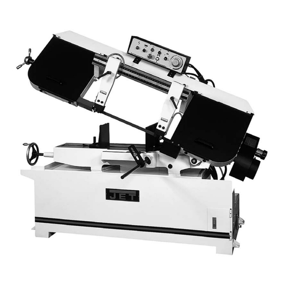
Semi-Automatic Band Saw
Model HBS-1321W
WALTER MEIER (Manufacturing) Inc.
427 New Sanford Road
LaVergne, Tennessee 37086
Part No. M-414471
Ph.: 800-274-6848
Revision G2 01/2012
www.waltermeier.com
Copyright © 2012 Walter Meier (Manufacturing) Inc.
Advertisement
Table of Contents

Related Manuals for Jet HBS-1321W


Summary of Contents for Jet HBS-1321W
- Page 1 This .pdf document is bookmarked Operating Instructions and Parts Manual Semi-Automatic Band Saw Model HBS-1321W WALTER MEIER (Manufacturing) Inc. 427 New Sanford Road LaVergne, Tennessee 37086 Part No. M-414471 Ph.: 800-274-6848 Revision G2 01/2012 www.waltermeier.com Copyright © 2012 Walter Meier (Manufacturing) Inc.
-
Page 2: Warranty
Walter Meier Authorized Service Centers can authorize warranty repair, assist you in obtaining parts, or perform routine maintenance and major repair on your JET® tools. For the name of an Authorized Service Center in your area call 1-800-274-6848. -
Page 3: Warnings
Read and understand the entire instruction manual before attempting assembly or operation. • All JET bandsaws are designed and intended for use by properly trained and experienced personnel only. If you are not familiar with the proper and safe operation of a bandsaw, do not use until proper training and knowledge have been obtained. -
Page 4: Table Of Contents
Specifications: Model: HBS-1321W Stock Number........................414471 Capacity: Round at 90° (in) ....................13” (330 mm) Round at 45° (in) ................... 10-1/2” (268 mm) Rectangle at 90° (in) ....... 10” x 21” (254x533 mm) and 13” x 19” (330x483 mm) Rectangle at 45° (in) ..............11-1/2” x 10-1/2” (292x268 mm) Throat Depth (in) ...................... -
Page 5: Uncrating And Cleanup
Uncrating and Cleanup Read and understand the entire manual before attempting setup or operation. Finish uncrating the saw and inspect for damage. If any damage has occurred, contact your local distributor. Remove all bolts attaching machine to shipping base. Leave packing material between vice clamps and saw head intact until bandsaw has been lifted to its final position. -
Page 6: Electrical Connections
3Ph. and is prewired 230 volt from the factory. Confirm power source available at the saw's location is the same as the saw is wired. To switch the HBS-1321W from 230V to 460V, the following items will have to be changed: Bandsaw must always be properly grounded. -
Page 7: Prior To Operation
See adjusting feed rate page 9. Prior to Operation 1. All JET bandsaws are designed and intended for use by properly trained and experienced personnel only. If you are not familiar with the proper and safe operation of a bandsaw, do not use until proper training and knowledge have been obtained. -
Page 8: Adjusting Vise Square To Blade
WARNING Disconnect machine from the power source before adjusting or changing vise position! Failure to comply may cause serious injury! Adjusting Vise Square to the Blade Position A 1. Place a machinist's square on the bed against the blade and the vise. The square should lie along the entire length of the vise and blade without a gap. -
Page 9: Changing Blade Speeds
Changing Blade Speeds Adjust the variable blade speed only while the machine is running. The dial (A, Fig. 6) sticking out of the belt cover (right side) controls the variable speeds between 66 FPM to 264 FPM. Semi-Automatic Arm Preset the height, which the arm stops when it raises automatically. -
Page 10: Changing Blades
Changing Blades WARNING Disconnect machine from the power source before making any adjustments or repairs! Failure to comply may result in serious injury! 1. Raise the saw arm approximately 6". 2. Disconnect machine from power source. 3. Open both wheel covers and clean chips out of both wheel housings. -
Page 11: Guide Roller Adjustment
Guide Roller Adjustment The bearings come pre-adjusted from the factory. If adjustment is needed follow the below steps: 1. Disconnect machine from the power source. 2. Loosen two hex socket cap screws (A, Fig. 9). 3. Move guide seat (B, Fig. 9) up or down until an approximate clearance of .003"... -
Page 12: Blade Tracking Adjustment
Blade Tracking Adjustment Since tracking can only be adjusted while machine is running, it is suggested that this adjustment be accomplished by qualified personnel that are familiar with this type of adjustment and the dangers associated with it. Blade tracking has been set at the factory and should require no adjustment. -
Page 13: Hydraulic Pump
To change gear box lubricant: Disconnect machine from the power source. Remove drain plug and allow lubricant to drain completely. The drain plug is located on lower front of gear case under right wheel cover. Remove drain plug with a hex wrench. -
Page 14: Bed And Base Assembly Breakdown & Parts List
Bed and Base Assembly... - Page 15 Parts List for the JET HBS-1321W Bandsaw Bed and Base Assembly Index Part Description Size Qty. 1 ..1321W-01 ......... Base ..................1 2 ..TS-1492061 ......Hex Cap Bolt ......M12x65 ........4 3 ..TS-1540081 ......Hex Nut........M12 ........4 4 ..
- Page 16 21 ..1321W-21 ......... Handle Wheel Assembly ............1 21-1 ..TS-0270031 ......Set Screw ......... 5/16"x3/8" ....... 2 21-2 ..1321W-21-2 ......Handle ..................1 22 ..1321W-22 ......... Rack ..................1 23 ..1321W-23 ......... Lead Screw Seat ..............1 23-2 ..
- Page 17 50 ..1321W-50 ......... Retaining Pin ................1 51 ..1321W-51 ......... Cylinder Assembly ..............1 51-1 ..1321W-51-1 ......Holder ..................1 52 ..1321W-52 ......... Cylinder Pin ................1 53 ..1321W-53 ......... Top Mounting Plate ..............1 54 ..
-
Page 18: Arm Assembly Breakdown & Parts List
Arm Assembly... - Page 19 Arm Assembly Index Part Description Size Qty. 8-1..1321W-08-1 ......Hose Fitting................2 8-2..1321W-08-2 ......Hose Clamp ................6 8-4..1321W-08-4 ......On/Off Valve ................3 80 ..1321W-80 ......... Blade Wheel Cover - R............. 1 80-1 ..
- Page 20 103 ..TS-1524041 ......Set Screw ......... M8x16 ........4 104 ..1321W-104 ....... Blade Guide Assembly-L ............2 105 ..1321W-105 ....... Blade Guide Assembly-R ............2 106 ..1321W-106 ....... Connector ................2 107 ..1321W-107 ....... Cu Connector ................2 108 ..
- Page 21 149-2 ... TS-1551041 ......Spring Washer ......M6 .......... 2 149-3 ... TS-1550041 ......Washer ........M6 .......... 2 150 ..1321W-150 ....... Control Box ................1 150-1 ... TS-1482021 ......Hex Cap Bolt ......M6x12 ........4 150-2 ... TS-1551041 ......Spring Washer ......M6 .......... 4 150-3 ...
-
Page 22: Gearbox Assembly Breakdown & Parts List
.... 1321W-181B1 ......Laser Guide with Bracket (not shown) ........1 .... 1321W-181B2 ......Transformer with Power Cord (not shown) ......... 1 .... 1321W-181B3 ......Bracket for Laser Guide (not shown) ......... 1 Gear Reduce Box Assembly Index Part Description Size Qty. -
Page 23: Wiring Diagram And Symbols
Wiring Diagram... - Page 24 Wiring Diagram Symbol Glossary Symbol Description Part Number Cut off Limit Switch 1321W-45 Roller Limit Switch 1321W-45-1 Emergency Switch 1321W-156 Start Switch 1321W-154 Arm Down Switch 1321W-158 Arm Up Switch 1321W-157 Stop Switch 1321W-155 Power Indicator Light 1321W-153 Control Transformer 1321W-76 3A Fuse 1321W-77-1...
Need help?
Do you have a question about the HBS-1321W and is the answer not in the manual?
Questions and answers