Webasto Thermo 90 Workshop Manual
Hide thumbs
Also See for Thermo 90:
- Workshop manual (43 pages) ,
- Installation instructions manual (41 pages) ,
- Operating instructions (3 pages)

Related Manuals for Webasto Thermo 90


Summary of Contents for Webasto Thermo 90
- Page 1 Water Heaters Workshop Manual Thermo 90 Thermo 90-TRS (Transport of hazardous goods) Thermo 90 S Thermo 90 S-TRS (Transport of hazardous goods) Type BW 80 (Fuel) Type DW 80 (Diesel) 09/2001...
-
Page 2: Table Of Contents
Switch-off ............................... 301 Functions of the Heater in TRS Vehicles....................301 Malfunctions............................303 3.6.1 Switch-off upon Failure........................ 303 3.6.2 Diagnosis after Switch-off upon Failure (Thermo 90) ..............303 3.6.3 Diagnosis after Switch-off upon Failure (Thermo 90 S)............... 303 Technical Data..............................401 Troubleshooting General .............................. -
Page 3: Adjustments
List of Contents Thermo 90 Functional Tests General ..............................601 Adjustments ............................601 6.2.1 Adjustment of the CO Contents ....................601 Components Testing..........................601 6.3.1 Temperature Sensor Resistance Check..................601 6.3.2 Glow Plug Resistance Test......................601 6.3.3 Flame Sensor Resistance Test....................601 6.3.4 Combustion Air Fan Test ...................... - Page 4 Thermo 90 List of Contents Repair General ..............................901 9.1.1 Work on Components after Disassembly ..................901 Disassembly and Assembly........................902 9.2.1 Electrical Connections ......................... 902 9.2.2 Replacement of Circulation Pump ....................903 9.2.3 Replacement of Temperature Limiter ..................904 9.2.4 Replacement of Temperature Sensor ..................
- Page 5 Circuit Diagram Automatic Control for Thermo 90, 12 and 24 V with Triple Timer ........702 Circuit Diagram Automatic Control Thermo 90-TRS, 24 V ................ 703 Circuit Diagram Automatic Control for Thermo 90 S, 12 and 24 V with Standard Timer ......704 Circuit Diagram Automatic Control for Thermo 90 S-TRS, 24 V..............705 Circuit Diagram Automatic Control for Thermo 90 S-TRS, 24 V without Auxiliary Drive ......
-
Page 6: Note
This repair shop manual is intended to support "General Safety Regulations" beyond the scope of these familiarised personnel in the repair of Thermo 90 and regulations are detailed in the following. Thermo 90 S for the Diesel and fuel type. -
Page 7: Legal Provisions For Installation
For the installation of the Thermo 90-TRS or Legal Provisions for Installation Thermo 90 S-TRS in vehicles used for the transportation of dangerous goods, in addition to the StVZO, the For testing the heater in accordance with § 19, 20, or 21... -
Page 8: Corrections And Improvements
Thermo 90 1 Introduction • Installation Instructions for Webasto fuel tanks for the Corrections and Improvements fuel supply of water heaters in vehicles: In busses the installation is not permitted in the Deficiencies, improvements, or proposals for correction of passengers or driver's compartment. - Page 9 1 Introduction Page free for notes...
-
Page 10: Heat Exchanger
On the Thermo 90 S heater the control unit may also be Dependent on the deviation of the current coolant flanged to the combustion air fan. -
Page 11: General Description
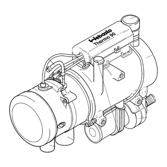
10 Inlet, Combustion Air 11 Control unit (may also be located externally in the vehicle) Heater Thermo 90 S Combustion Air Fan Heat Exchanger The combustion air fan delivers the air required for The heat exchanger dissipates the heat provided by combustion from the combustion air inlet to the burner combustion to the coolant circuit. -
Page 12: Combustion Tube
The control unit is the central controlling device for functional sequencing and monitoring of the combustion operation. It is located externally in the vehicle, but may also be flanged to the combustion air fan on Thermo 90 S Flame Sensor heaters. - Page 13 2 General Description Thermo 90 Page free for notes...
-
Page 14: Heating Operation
Thermo 90 3 Functional Description Functional Description (Fig. 301) Switch-on When operating the push button "Immediate Heating", the "Operating Indicator" on the timer illuminates by activation with the switch, the operating indicator integrated in the switch illuminates. Circulation pump, glow plug, and combustion air fan are put into operation. -
Page 15: Switch-Off
Functions of the Heater in TRS off without run-down (overheating possible). Fig. 301 Functional Sequence Functional Sequence for Thermo 90 Dosing Pump Priming 5 – 7 sec. (1) Dosing Pump / Part Load (1/4) Flame Sensor Take-over... -
Page 16: Malfunctions
After five short signals the following long flash pulses are counted: Setting of Control Temperatures Thermo 90 S Connection of signal "motor on"/ "motor off" (terminal D+) No start (after 2 start attempts) to the control unit (connector X12, contact 7) will enable Flame-out during operation (repeated >... - Page 17 3 Functional Description Thermo 90 3.6.3 Diagnosis after Switch-off upon Failure (Thermo 90 S) When equipped with a standard timer an error will cause an output to the timer display: F 01 No start (after 2 start attempts) F 02 Flame-out during operation (repeated >...
- Page 18 Thermo 90 3 Functional Description Page free for notes...
-
Page 19: Technical Data
SL 10 % 10.6 % 11.3 % Dimensions heater Length 310 mm (355 mm) (Tolerance ± 3 mm) Width 133 mm Height 220 mm Weight 4.8 kg Thermo 90-TRS 24 Volts only Thermo 90-S with control unit mounted on heater... - Page 20 4 Technical Data Thermo 90 Page free for notes...
-
Page 21: Troubleshooting 5.1 General
The following defects are not included in the trouble shooting procedures. Before troubleshooting, check for and eliminate these defects: This section describes troubleshooting procedures for the Water Heater Thermo 90 and Thermo 90 S. • corrosion on connector • loose contact on connector CAUTION •... -
Page 22: Failure Symptoms After Switch-Off Upon Failure
5 Troubleshooting Thermo 90 Failure Symptoms after Switch-off The heater Thermo 90 S with standard timer outputs errors to the timer display for indication (see 3.6.3). upon Failure The following table may also be used as representative reference. NOTE When operated with a switch the type of failure is indicated by a flash code of the operation indicator light during heater run-down. -
Page 23: Visual Inspection For Assessment Of Burner Condition
Thermo 90 5 Troubleshooting Failure Symptom Failure Symptom Remedy 8 Flash pulses Wiring Check wiring for damage, (combustion air fan defective) open connections or short circuit Combustion air fan defective Replace combustion air fan 9 Flash pulses Wiring Check wiring for damage,... -
Page 24: Rear Wall With Metal Evaporator
5 Troubleshooting Thermo 90 5.4.2 Rear Wall with Metal Evaporator 5.4.3 Combustion Chamber • The pilot flame exit bore (Fig. 504) must not be • The combustion chamber (Fig. 505) should not be clogged, otherwise there will be no start. - Page 25 On the Thermo 90 S the check is performed by means of the PC heater diagnosis. 990 ... 1010 Ω Resistance at 25° C: Test current: <...
- Page 26 6 Functional Tests Thermo 90 Page free for notes...
-
Page 27: Combustion Air Fan (See 9.2.5)
Thermo 90 S with – standard timer – TRS equipment – TRS equipment without auxiliary drive Fig. 701 shows the pin assignment (X1) for Thermo 90 and Thermo 90 S. CAUTION The –poles must not be looped or reversed as some components are controlled by negative polarity. -
Page 28: Circuit Diagrams
P Relay (in item A2) for circulation pump Connection 2-pole Relay for vehicle blower Dosing Pump Relay only required for battery switch in minus Fig. 702 Circuit Diagram Automatic Control for Thermo 90, 12 and 24 V with Triple Timer... - Page 29 20 mA Flame indication (option) Dosing Pump Relay (in item A2) Master relay Relay (in item A2) for circulation pump Relay for vehicle blower Motor Combustion air fan Motor Circulation pump Motor Vehicle blower Fig. 703 Circuit Diagram Automatic Control Thermo 90-TRS, 24 V...
- Page 30 LED red (in item P2) Illumination instant heat switch, standby indication, on indication Relay for vehicle blower Motor Combustion air fan Motor Circulation pump Motor Vehicle blower Fig. 704 Circuit Diagram Automatic Control for Thermo 90 S, 12 and 24 V with Standard Timer...
- Page 31 Motor Combustion air fan Motor Circulation pump Motor Vehicle blower Switch ON / OFF Isolation Switch 1-pole or 2-pole Emergency off switch electr. or pneum. Fig. 705 Circuit Diagram Automatic Control for Thermo 90 S-TRS, 24 V...
- Page 32 Motor Combustion air fan Motor Circulation pump Motor Vehicle blower Switch ON / OFF Isolation Switch 1-pole or 2-pole Emergency off switch electr. or pneum. Fig. 706 Circuit Diagram Automatic Control for Thermo 90 S-TRS, 24 V without Auxiliary Drive...
-
Page 33: Servicing 8.1 General
Thermo 90 8 Servicing Servicing General This section describes the servicing procedures that may be performed with the heater installed. Work on the Heater Prior to performing any work, it is mandatory to disconnect the vehicle battery main lead. As long as the heater is... -
Page 34: Heater Test Run
8 Servicing Thermo 90 Heater Test Run WARNING The heater must not be operated, not even with timer, in enclosed areas like garages or workshops not equipped with an exhaust venting facility. Servicing Before or after each heating season the following... -
Page 35: Note
Thermo 90 8 Servicing NOTE Manufacturer mounts control unit of heaters Thermo 90 S to combustion air fan. With Check Valve and Thermostat 1 Heat Exchanger, Vehicle Heating System 2 Blower Switch Vehicle Heating System 3 Relay for Vehicle Blower... -
Page 36: Visual Inspections And Installation Regulations
S (m) pressure (bar) in fuel tank 0.00 – 0.10 As a rule, the coolant hoses supplied by Webasto together with the heater are to be used. Otherwise the 0.50 – 0.06 hoses must at least meet the requirements of DIN 73411. - Page 37 Gasket For fuel tapping from the supply or return line only the specific Webasto fuel tap, e.g. Ident. No. 470 910 for Ø 8 mm may be used. The fuel tap must be mounted so that the air or gas bubbles can escape towards the fuel tank.
-
Page 38: Dosing Pump
The fuel line joints are to be secured against loosening with hose clamps. Thermo 90, 12 Volt – Fuel 0-90° 0-90° 0° Thermo 90, 12 Volt and 24 Volt – Diesel DP 30 Installation Position Horizontal only Fig. 807 Dosing Pump, Installation Location and Attachment... -
Page 39: Fuel Filter
Webasto original parts. 8.6.4 Fuel Filter If there is the probability of contaminated fuel, only the Webasto filter, Order No. 487 171, may be used. The filter can be installed anywhere between the vertical and Exhaust exit direction horizontal positions, but must be installed in the direction nearly vertical 90°... -
Page 40: Removal And Installation
4. Secure connections for combustion air inlet and exhaust outlet on heater. NOTE On heater Thermo 90 S with control unit flanged to combustion air fan reconnect connectors X12 and X13 to control unit. 5. Connect plug of cable loom to heater. - Page 41 Thermo 90 8 Servicing Page free for notes...
-
Page 42: Repair 9.1 General
9.1.1.2 Visual Inspection This section describes the repairs that may be performed • Examine all components for damages (cracks, on the heater Thermo 90 when removed. Any further deformation, wear, etc.) and replace as necessary. disassembly will void the warranty. •... -
Page 43: Disassembly And Assembly
One of the newer models Thermo 90 shown. Older models have the cable of the temperature limiter located on the side. Heater Thermo 90 S may have the control unit located on the combustion air fan. Top Cover Supplier of Removal Tool (Order No. -
Page 44: Replacement Of Circulation Pump
One of the newer models Thermo 90 shown. Older models have the cable of the temperature limiter located on the side. Heater Thermo 90 S may have the control unit located on the combustion air fan not affecting the replacement of the circulation pump. -
Page 45: Replacement Of Temperature Limiter
9 Repair Thermo 90 9.2.3 Replacement of Temperature Limiter 9.2.4 Replacement of Temperature Sensor 9.2.3.1 Removal 9.2.4.1 Removal NOTE 1. Remove heater (see 8.7.1.1). Perform the following procedure only when the tempera- 2. Disconnect electrical connections (see 9.2.1.1). ture limiter needs replacement. - Page 46 One of the newer models Thermo 90 shown. Older models have the cable of the temperature limiter located on the side. Heater Thermo 90 S may have the control unit located on the combustion air fan not affecting the replacement of the temperature limiter and temperature sensor.
-
Page 47: Replacement Of Combustion Air Fan
2. Torque tighten screws (2) with 3 Nm ± 10%. NOTE NOTE On heater Thermo 90 S with flanged control unit On heater Thermo 90 S with flanged control unit install remove control unit as required. control unit as required. 5. Perform procedures on components after 3. -
Page 48: Replacement Of Burner, Flame Sensor, And Glow Plug
Thermo 90 9 Repair 9.2.6 Replacement of Burner, Flame Sensor, CAUTION When performing the following step ensure that cables of and Glow Plug flame sensor (7) and glow plug (6) are routed as shown in figure. 9.2.6.1 Removal 1. Remove heater (see 8.7.1.1). - Page 49 One of the newer models Thermo 90 shown. Older models have the cable of the temperature limiter located on the side. Illustration is also applicable for heater Thermo 90 S. Fig. 905 Replacement of Burner, Flame Sensor, and Glow Plug...
-
Page 50: Replacement Of Burner Head
6. Perform procedures on components after 5. Install heater (see 8.7.1.2). disassembly (see 9.1.1). NOTE One of the newer models Thermo 90 shown. Older models have the cable of the temperature limiter located on the side. Illustration is also applicable for heater Thermo 90 S. -
Page 51: Replacement Of Heat Exchanger
9 Repair Thermo 90 9.2.8 Replacement of Heat Exchanger 9.2.8.2 Installation 1. Clip connector housing onto heat exchanger and 9.2.8.1 Removal engage connector in connector housing. 2. Install burner head (see 9.2.7.2). 1. Remove heater (see 8.7.1.1). 3. Install burner, flame sensor, and glow plug 2. -
Page 52: Packaging/Storage And Shipping 10.1 General
10 Packaging/Storage and Shipping Packaging/Storage and Shipping 10.1 General The heater and its components shipped to Webasto Thermosysteme GmbH for inspection or repair are to be cleaned and packaged so that they are protected against damage during handling, transportation, and storage. - Page 53 10 Packaging/Storage and Shipping Thermo 90 Page free for notes 1002...
Need help?
Do you have a question about the Thermo 90 and is the answer not in the manual?
Questions and answers