Anritsu Site Master S251C User Manual
Anritsu site master antenna and cable analyzer user's guide model s251c
Hide thumbs
Also See for Site Master S251C:
- Maintenance manual (18 pages) ,
- Programming manual (34 pages)

Related Manuals for Anritsu Site Master S251C


Summary of Contents for Anritsu Site Master S251C
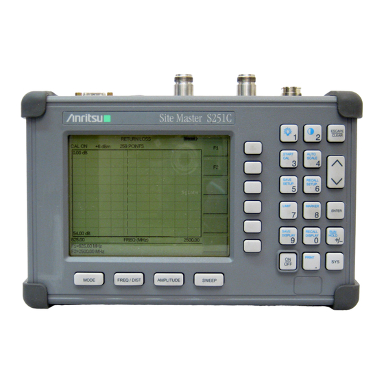
- Page 1 Site Master Model S251C Antenna and Cable Analyzer User's Guide Hand-Held Tester for Transmission Lines and other RF Components Color Front Cover only P/N: 00986-00045...
-
Page 3: Limitation Of Warranty
The Anritsu product(s) listed on the title page is (are) warranted against defects in materials and workmanship for one year from the date of shipment. Anritsu's obligation covers repairing or replacing products which prove to be defec- tive during the warranty period. Buyers shall prepay transportation charges for equipment returned to Anritsu for warranty repairs. -
Page 5: Table Of Contents
Table of Contents Chapter 1 - General Information Introduction ........1-1 Description . - Page 6 Saving a Setup ........3-5 Recalling a Setup.
- Page 7 Appendix A - Reference Data Coaxial Cable Technical Data......A-1 Appendix B - Windowing Introduction ........B-1 Examples .
-
Page 8: Chapter 1 - General Information
Distance-To-Fault (DTF) measurement instrument that includes a built-in synthesized signal source. The S251C includes a keypad to enter data and a VGA (640 ´ 480) liquid crystal display (LCD) to provide graphic indications of SWR, RL (dB) over the selected frequency range and distance. -
Page 9: Options
Option 10A ¾ Add Bias Tee · Optional Accessories · Anritsu Precision N (m) Open/Short/Load, 42 dB, Part No. OSLN50LF · Anritsu Precision N (f) Open/Short/Load, 42 dB, Part No. OSLNF50LF · Anritsu Precision N (m) Short/Open, Part No. 22N50 ·... -
Page 10: Performance Specifications
· Armored Test Port Extension Cable, 1.5 meter, N (m) to N (m), Part No. 15NN50-1.5C · Armored Test Port Extension Cable, 3.0 meter, N (m) to N (m), Part No. 15NN50-3.0C · Armored Test Port Extension Cable, 5.0 meter, N (m) to N (m), Part No. - Page 11 Chapter 1 General Information Table 1-1. Performance Specifications (1 of 2) Specifications are valid when the unit is calibrated at ambient temperature after a 5 minute warmup. Description Site Master: S251C Frequency Accuracy (RF Source Mode): Frequency Resolution: SWR: Range Resolution Return Loss:...
- Page 12 Table 1-2. Performance Specifications (2 of 2) Cable Insertion Loss: Range Resolution Bias Tee input voltage: output current: General Internal Memory: Trace Memory Instrument config. RS-232 Electromagnetic Compatibility Power Supply: External DC Input Temperature: Storage Operation Weight: Dimensions: * ±2 ppm/D°C from 25°C ** Fault location is accomplished by inverse Fourier Transformation of data taken with the Site Master.
-
Page 13: Preventive Maintenance
Chapter 1 General Information Preventive Maintenance Site Master preventive maintenance consists of cleaning the unit and inspecting and clean- ing the RF connectors on the instrument and all accessories. Clean the Site Master with a soft, lint-free cloth dampened with water or water and a mild cleaning solution. -
Page 14: Annual Verification
Annual Verification Anritsu recommends an annual calibration and performance verification of the Site Master and the OSL calibration components by local Anritsu service centers. Anritsu service cen- ters are listed in Table 1-2 on the following page. The Site Master itself is self-calibrating, meaning that there are no field-adjustable compo- nents. - Page 15 Telephone: (06) 50-2299-711 ANRITSU ELECTRONICA LTDA. FAX: 06-50-22-4252 Praia de Botafogo 440. Sala 2401 CEP22250-040,Rio de Janeiro,RJ, Brasil JAPAN Telephone: 021-527-6922 ANRITSU CUSTOMER SERVICE LTD. FAX: 021-53-71-456 1800 Onna Atsugi—shi Kanagawa-Prf. 243 Japan Telephone: 0462-96-6688 CANADA FAX: 0462-25-8379 ANRITSU INSTRUMENTS LTD.
-
Page 16: Chapter 2 - Functions And Operations
The Site Master can also be powered by a 12.5 VDC external source. The external source can be either the Anritsu AC-DC Adapter (P/N 40-115) or 12.5 Vdc Automotive Cigarette Lighter Adapter (P/N 806-62). Both items are standard accesso- ries. -
Page 17: Front Panel Overview
The current soft key function is indicated in the active function block to the right of the display. The locations of the different keys are illustrated in Figure 2-1. Active Function Block Site Master S251C MODE FREQ/DIST AMPLITUDE Function Hard Keys Figure 2-1. -
Page 18: Function Hard Keys
Function Hard Keys MODE Opens the mode selection box (below). Use the Up/Down arrow key to select a mode. Press the ENTER MEASUREMENT MODE FREQ - SWR RETURN LOSS CABLE LOSS - ONE PORT INSERTION LOSS (+6 dBm) INSERTION GAIN (–30 dBm) DTF - RETURN LOSS POWER MONITOR... -
Page 19: Keypad Hard Keys
ENTER Implements the current action or parameter selection. Turns the Anritsu Site Master on or off. When turned on, the system state at the last turn-off is restored. If the ESCAPE/CLEAR key is held down while the ON/OFF key is pressed, the factory preset state will be restored. - Page 20 The following keypad hard key functions are printed in blue on the keypad keys. Turns the liquid crystal display (LCD) back-lighting ON or OFF. (Leaving back lighting off conserves battery power.) LCD Contrast adjust. Use the Up/Down arrow key and the display contrast.
-
Page 21: Soft Keys
Chapter 2 Functions and Operations Soft Keys Each function key opens a set of soft key selections. Each of the soft keys has a correspond- ing soft key label area on the display. The label identifies the function of the soft key for the current Mode selection. - Page 22 FREQ/DIST MODE=DTF: SOFTKEYS: DTF AID MORE LOSS PROP CABLE WINDOW BACK Figure 2-4. Distance to Fault Mode Soft Key Labels Chapter 2 Functions and Operations AMPLITUDE SWEEP RESOLU- TION SINGLE BOTTOM SWEEP TRACE MATH TRACE OVERLAY ON/OFF SELECT TRACE LIST PAGE UP PAGE BACK...
- Page 23 Chapter 2 Functions and Operations FREQ/DIST Displays the frequency and distance menu depending on the measurement mode. Frequency Provides for setting sweep frequency end points when Menu Selected frequency values may be changed using the keypad or Up/Down arrow key. —...
- Page 24 AMPLITUDE Displays the amplitude or scale menu depending on the measurement mode. Amplitude Provides for changing the display scale. Selected values may be changed using Menu the Up/Down arrow key or keypad. Choosing AMPLITUDE keys, below, to be displayed and the corresponding values to be shown in the message area.
-
Page 25: Power Monitor Menu (Option 5)
Chapter 2 Functions and Operations Power Monitor Menu (Option 5) Selecting POWER MONITOR to be displayed and the corresponding values shown in the message area. MODE=POWER MONITOR: Figure 2-5. Power Monitor Mode Soft Key Labels — Toggles between dBm and Watts. UNITS —... -
Page 26: Examples
RF Source Menu RF Source mode provides an RF Out source that can be used, for example, in the alignment of dish antennas. Selecting RF SOURCE scribed below, to be displayed: MODE=RF SOURCE: Figure . RF Source Softkeys — Allows setting of the RF source frequency. Use the keypad number FREQ keys to enter a frequency, or use the Up/down arrow key to adjust the fre- quency in 10 kHz steps. - Page 27 Chapter 2 Functions and Operations Pressing LIMIT on the data keypad activates a menu of limit related functions. LIMIT Use the corresponding softkey to select the desired limit function. Then use the Up/Down arrow key to change its value, which is displayed in the message area at the bottom of the display.
- Page 28 EDIT — Opens the selected marker parameter for data entry. Press when data entry is complete or ENTER value. DELTA (Mx-M1) — Displays delta amplitude value as well as delta fre- quency or distance for the selected marker with respect to the M1 marker. MARKER TO PEAK —...
- Page 29 Chapter 2 Functions and Operations SEGMENT 3 SEGMENT 4 SEGMENT 5 BACK LIMIT BEEP — Turns the audible limit beep indicator on or off. Displays the System menu softkey selections. OPTIONS — Displays a second level of functions: — Select the unit of measurement (English or metric). UNITS PRINTER arrow key and...
-
Page 30: Symbols
Integrator Failure. Intermittent integrator failure may be caused by inter- ference from another antenna. Persistent integrator failure indicates a need to return the Site Master to the nearest Anritsu service center for repair. Lock fail indication. Check battery. (If the Site Master fails to lock with a fully charged battery, call your Anritsu Service Center.) -
Page 31: Error Codes
The EEPROM test on the Site Master main board has failed. If condi- tion persists, call your Anritsu Service Center. Note: A listing of current Anritsu service centers is given in Table 1-2 , page 1-8. 2 - 16 Description... -
Page 32: Range Errors
Range Errors A listing of Range Error messages is given in Table 2-3. Table 2-3. Range Error Messages (1 of 2) Error Message RANGE The start (F1) frequency is greater than the stop (F2) frequency. ERROR:F1 > F2 RANGE The start (D1) distance is greater than the stop (D2) distance. ERROR:D1 >... -
Page 33: Battery Information
The battery can be charged while installed in the Site Master. Step 1. Turn the Site Master off. Step 2. Connect the AC-DC adapter (Anritsu part number: 40-115) to the Site Master charging port. Step 3. Connect the AC adapter to a 120 VAC or 240 VAC power source as appropriate for your application. -
Page 34: Battery Charge Indicator
The NiMH battery will last longer and perform better if allowed to completely discharge before recharging. For maximum battery life, it is recommended that the NiMH battery be completely discharged and recharged once every three months. Battery Charge Indicator When the AC-DC adapter is unplugged from the Site Master, the battery indicator symbol will be continuously displayed at the top left corner of the Site Master display (Figure ). -
Page 35: Important Battery Information
· Recharge the battery only in the Site Master or in an Anritsu approved charger. · When the Site Master or the charger is not in use, disconnect it from the power source. -
Page 36: Chapter 3 - Getting Started
Power On Procedure The Anritsu Site Master is capable of up to 2.5 hours of continuous operation from a fully charged, field-replaceable battery. Built-in energy conservation features allow battery life to be extended over an eight-hour workday. -
Page 37: Select The Frequency Or Distance
Chapter 3 Getting Started Select the Frequency or Distance Regardless of the calibration method used, the frequency range for the desired measure- ments must be set before calibrating the Site Master. The following procedure selects the frequency range for the calibration. Step 1. -
Page 38: Calibration Procedure - Single Port
Calibration Procedure - Single Port Check that the “CAL OFF” message is displayed in the upper left corner of the display. This indicates that the Site Master has not been calibrated. The following procedure details how to perform the calibration. RFOUT/REFLECTION TEST PORT MODE... -
Page 39: Calibration Procedure - Dual Port
The message CONNECT OPEN TO RF Out key. The messages Mea- ENTER key. The message Measuring THRU will appear. LOAD OPEN SHORT (OPTIONAL) LOAD TEST PORT CABLE (OPTIONAL) RF OUT TEST PORT Site Master S251C ESCAPE CLEAR START AUTO SCALE SAVE RECALL SETUP SETUP LIMIT MARKER... -
Page 40: Setting The Scale
Setting the Scale Auto Scale The Site Master can automatically set the scales to the minimum and maximum values of the measurement on the y-axis of the display. This function is particularly useful for mea- surements in SWR mode. To automatically set the scales: Step 1. -
Page 41: Recalling A Display
Chapter 3 Getting Started Step 1. Press the SAVE DISPLAY age. Step 2. Use the soft keys to enter a label for the saved trace. For example, to save a display with the name “TX1 RETURN LOSS” press the soft key group that contains the letter “T” then press the “T” soft key. Press the soft key group that contains the letter “X”... -
Page 42: Set The Distance And Cable Type
Set the Distance and Cable Type In Distance-To-Fault (DTF) mode, the length of the transmission line (distance) and cable type are selected. The cable type determines the velocity propagation and cable attenuation factor. The following procedure can be used to set the distance and select the appropriate cable type. -
Page 43: Printing
Printing is accomplished by selecting an available printer and pressing the print key as de- scribed below. Refer to the particular printer operating manual for specific printer settings. Printing a Screen Step 1. Connect the printer as shown in Figure 3-4. Site Master S251C START SAVE SETUP... -
Page 44: Printer Switch Settings
Switch Set the switches on the serial-to-parallel interface cable to the HP Deskjet 350 ink jet printer as follows: soft key and select from the displayed menu of supported key. (Figure 3-6). Site Master S251C ESCAPE CLEAR PRINTER START AUTO... -
Page 45: Using The Soft Carrying Case
Using the Soft Carrying Case The soft carrying case has been designed such that the strap can be unsnapped to allow the case to be easily oriented horizontally; thus allowing the Anritsu controls to be more easily accessed (Figure 3-7). -
Page 46: Chapter 4 - Cable & Antenna Analysis
Chapter 4 Cable & Antenna Analysis Introduction This chapter provides a description of cable and antenna measurements in one port and two port modes. Measurements include line sweeping fundamentals and line sweeping measure- ment procedures, available when the Site Master is in frequency or DTF mode. One Port Measurements Line Sweep Fundamentals In wireless communication, the transmit and receive antennas are connected to the radio... -
Page 47: Information Required For A Line Sweep
Chapter 4 Measurements The performance of a transmission feed line system may be affected by excessive signal re- flection and cable loss. Signal reflection occurs when the RF signal reflects back due to an impedance mismatch or change in impedance caused by excessive kinking or bending of the transmission line. -
Page 48: Chapter 4 Measurements
Site Master Model S251C Precision Open/Short, Anritsu 22N50 or Precision Open/Short/Load, Anritsu OSLN50LF Precision Load, Anritsu SM/PL Test Port Extension Cable, Anritsu 15NNF50-1.5C Optional 510-90 Adapter, DC to 7.5 GHz, 50 ohm, 7/16 (F)-N (M) Device Under Test Transmission Feed Line with Antenna Procedure Step 1. - Page 49 Chapter 4 Measurements Figure 4-2 is an example of a typical system return loss trace: Figure 4-2. Typical System Return Loss Trace NOTE: The system sweep trace should appear at an approximate return loss of 15 dB (±3 dB) on the display. In general, a 15 dB return loss is measured in the passband of the antenna system.
-
Page 50: Insertion Loss Measurement
Site Master Model S251C Precision Open/Short, Anritsu 22N50 or Precision Open/Short/Load, Anritsu OSLN50LF Precision Load, Anritsu SM/PL Test Port Extension Cable, Anritsu 15NNF50-1.5C Optional 510-90 Adapter, DC to 7.5 GHz, 50 ohm, 7/16(F)-N(M) Device Under Test Transmission Feed Line with Short Procedure - Cable Loss Mode Step 1. - Page 51 Chapter 4 Measurements Step 14. Verify the measured insertion loss against the calculated insertion loss: First Jumper LDF4-50A Main Feeder LDF5-50A Top Jumper LDF4-50A The number of connector pairs (3) times the loss per pair (in dB) equals the con- nector loss: 3 ´...
- Page 52 Procedure - Return Loss Mode Step 1. Press the MODE Step 2. Select FREQ-RETURN LOSS using the Up/Down arrow key and press ENTER Step 3. Set the start and stop frequencies, F1 and F2, as described on page 3-2. Step 4. Connect the Test Port Extension cable to the RF Out port and calibrate the Site Master as described on page 3-2.
-
Page 53: Distance-To-Fault (Dtf) Transmission Line Test
Site Master Model S251C Precision Open/Short, Anritsu 22N50 or Precision Open/Short/Load, Anritsu OSLN50LF Precision Load, Anritsu SM/PL Test Port Extension Cable, Anritsu 15NNF50-1.5C Optional 510-90 Adapter, DC to 7.5 GHz, 50 ohm, 7/16(F)-N(M) Device Under Test Transmission Feed Line with Load Procedure - DTF-Return Loss Mode The following steps explain how to make a DTF measurement in return loss mode. - Page 54 Figure 4-5 shows an example of a typical DTF return loss trace. Figure 4-5. Typical DTF Return Loss Trace In the above example: Marker M1 marks the first connector, the end of the Site Master phase stable Test Port Extension cable. (M1 = 38.42 dB, 3.2 ft.) Marker M2 marks the first jumper cable.
-
Page 55: Antenna Subsystem Return Loss Test
Site Master Model S251C Precision Open/Short, Anritsu 22N50 or Precision Open/Short/Load, Anritsu OSLN50LF Precision Load, Anritsu SM/PL Test Port Extension Cable, Anritsu 15NNF50-1.5C Optional 510-90 Adapter, DC to 7.5 GHz, 50 ohm, 7/16(F)-N(M) Device Under Test Antenna Sub Assembly Procedure Step 1. - Page 56 Chapter 4 Measurements The following trace is an example of an antenna return loss trace. Figure 4-6. Antenna Return Loss Trace Calculate the threshold value and compare the recorded Lowest Return Loss to the calcu- lated threshold value. log VSWR Maximum Return Loss = VSWR NOTE: VSWR is the antenna manufacturer’s specified VSWR.
-
Page 57: Two Port Measurements
TMA-DD¾A dual-duplex tower mounted amplifier used for radios systems with a single transmission line connection for transmit and receive. These systems are com- monly called transceivers. TMA-D (Bias Tee) S251C S251C RF OUT RF IN Figure 4-7. Types of Tower Mounted Amplifiers During installation of the TMA, the following tests should be conducted: Antenna Subsystem Return Loss Testing to verify antenna performance. -
Page 58: Tma Measurements
TMA Measurements Required Equipment Site Master Model S251C Option 10A, Bias Tee External Power Supply 40-115 Test Port Extension Cable, Anritsu 15NNF50-1.5C N (m) to 7 (m) Adapters Device Under Test TMA-S Procedure Step 1. Connect the External Power Supply (40-115) to the Site Master. - Page 59 Chapter 4 Measurements key, then OPTIONS, then BIAS TEE to turn on the bias tee volt- Step 8. Press the age. The gain is the level change before and after the bias tee voltage is turned Step 9. Press the AUTO SCALE bottom scale, to display the gain level.
- Page 60 For a TMA-DD amplifier, TMA-DD RX/TX TEST PORT CABLE TEST PORT CABLE (OPTIONAL) (OPTIONAL) RF IN TEST PORT RF OUT TEST PORT (BIAS TEE) Site Master S251C ESCAPE CLEAR START AUTO SCALE SAVE RECALL SETUP SETUP...
- Page 61 Chapter 4 Measurements Marker M1 indicates the receive band of the tower mounted amplifier. The level above the 0 dB reference level is the gain of the TMA. Marker M2 indicates the transmit band of the amplifier where there is no gain. M1: 12.17 dB @ 1882.36 MHz 1825 1850...
- Page 62 For a TMA-D amplifier, TMA-D RX TX ANT TEST PORT CABLE TEST PORT CABLE (OPTIONAL) (OPTIONAL) RF IN TEST PORT RF OUT TEST PORT (BIAS TEE) Site Master S251C ESCAPE CLEAR START AUTO SCALE SAVE RECALL SETUP SETUP...
- Page 63 Chapter 4 Measurements Marker M1 indicates the receive band of the tower mounted amplifier. The level above the 0 dB reference level is the gain of the TMA. Marker M2 indicates the transmit band of the amplifier where there is no gain. Figure 4-14.
-
Page 64: Antenna To Antenna Isolation
Antenna to Antenna Isolation Introduction Measuring antenna-to-antenna isolation between adjacent systems is very important when deploying multiple systems on the same tower. It helps to determine the potential threat of interfering signals and maximizes the capacity of the base station. An example of adjacent PCS systems is shown in Figure 4-15. -
Page 65: Antenna-To-Antenna Isolation Measurement
The Insertion Gain Mode (–30 dBm level) does not output enough power to provide an accurate measurement of Antenna-to-Antenna isolation . Required Equipment Site Master Model S251C Test Port Extension Cable, Anritsu 15NNF50-1.5C (2 each) Adapter, Anritsu 36NN50A Procedure Step 1. Press the MODE Step 2. - Page 66 LIMIT Figure 4-17 displays a typical antenna isolation measurement display. R F In p u t R F O u tp u t Site Master S251C S ite Mas ter S 251C Figure 4-17. Typical Antenna Isolation Measurement Display Typical antenna-to antenna isolation measurements are made between –50 dB and –100 dB below the 0 dB reference line established by the 2-port calibration.
-
Page 67: Chapter 5 - Site Master Software Tools
Chapter 5 Site Master Software Tools Introduction This chapter provides a description of the Site Master Software Tools provided with the Site Master. Site Master Software Tools (SMST) is a Windows 95/98/NT4/2000/ME pro- gram for cable and antenna trace analysis. The program help function provides on screen instructions on display modification, trace overlay, and multiple plot printing. -
Page 68: Chapter 5 Software Tools Program
Chapter 5 Software Tools Program Installation To install the Site Master Software Tools program: Step 1. Insert the Anritsu Site Master Software Tools disk in the CDROM drive. Step 2. From the Windows Start menu, select Step 3. Type: X:\Setup.exe Step 4. -
Page 69: Interface Cable Installation
Communication between the Site Master and the PC is accomplished over a null modem se- rial cable provided with the Site Master (Anritsu part number 800-441). Step 1. Install the null modem serial interface cable to the Serial Interface connector on the Site Master Test Connector Panel. -
Page 70: Plot Capture
Chapter 5 Software Tools Program Plot Capture To open the plot capture menus, select the capture icon on the button bar, or select the drop down menu from the menu bar. ture Select Capture to Screen to download traces to the PC. Highlight a folder, or highlight individual traces within a folder, to be downloaded to the PC. -
Page 71: Trace Overlay Or Plot Overlay
Markers Markers M1 through M6 can be activated from the Plot Properties menu. The six active markers can be displayed on the plot to help identify faults from the line sweep data. Misc. The Miscellaneous tab allows adjustment of the Plot/Limit Line Width and the setting of the Plot Footer. -
Page 72: Custom Cable List
Chapter 5 Software Tools Program Step 3. Exit the Site Master Software Tools program and open the target application (Microsoft Word, etc.). Step 4. Select and then Edit file or a bitmap. Saving a Plot to a Spreadsheet Plots can be saved as a text file (.txt) which can then be imported into a spreadsheet program. -
Page 73: Creating A Database
Uploading a Cable List After custom cable list has be created in Site Master Software Tools it can upload it to the Site Master. The serial communication null modem cable must be connected from the Site Master to the PC. In the Cable Editor, select Tools load with a message "... -
Page 74: Coaxial Cable Technical Data
Appendix A Reference Data Coaxial Cable Technical Data Table A-1 provides a standard listing of common coaxial cables along with their Relative Propagation Velocity and Nominal Attenuation values in dB/m @1000, 2000, and 2500 MHz. Table A-1. Coaxial Cable Technical Data (1 of 3) Manufacturer Cable Type Andrew... - Page 75 Table A-1. Coaxial Cable Technical Data (2 of 3) Manufacturer Cable Type Belden RG214 Belden RG223 Cablewave HCC12-50J Cablewave HCC78-50J Cablewave HCC158-50J Cablewave HCC300-50J Cablewave HCC312-50J Cablewave HF 4-1/8” Cu2Y Cablewave HF 5” Cu2Y Cablewave HF 6-1/8” Cu2Y Cablewave FLC 38-50J Cablewave FLC 12-50J Cablewave...
- Page 76 Table A-1. Coaxial Cable Technical Data (3 of 3) Manufacturer Cable Type NK Cables RF 2 ¼” -50 RF 2 ¼” -50 NK Cables RF 2 ¼” -50 NK Cables NK Cables RFF 3/8” -50 RFF 3/8” -50 NK Cables RFF 3/8”...
-
Page 77: Appendix B Windowing
Appendix B Windowing Introduction The Distance sub-menu (page 2-8) provides for setting the cable loss and relative propaga- tion velocity of the coaxial cable. The WINDOW key opens a menu of FFT windowing types for the DTF calculation. The theoretical requirement for inverse FFT is for the data to extend from zero frequency to infinity. - Page 78 Figure B-2. Nominal Side Lobe Windowing Example Figure B-3. Low Side Lobe Windowing Example...
- Page 79 Appendix B Windowing Figure B-4. Minimum Side Lobe Windowing Example B-3/B-4...
Need help?
Do you have a question about the Site Master S251C and is the answer not in the manual?
Questions and answers