
Related Manuals for Advantech MIC-5332


Summary of Contents for Advantech MIC-5332
-
Page 1: User Manual
User Manual MIC-5332 AdvancedTCA® 10GbE Dual Socket CPU Blade with Intel® Xeon® E5-2600 series EP Processors... -
Page 2: Revision History
Revision History Revision Brief Description of Changes Date of Issue Index Initial Draft November 2011 Modification April 11 , 2012 Modification June 15 , 2012 Modification July 16 , 2012... -
Page 3: Product Warranty (2 Years)
Because of Advantech’s high quality-control standards and rigorous testing, most of our customers never need to use our repair service. If an Advantech product is defective, it will be repaired or replaced at no charge during the warranty period. For out-of-warranty repairs, you will be billed according to the cost of replacement materials, service time and freight. -
Page 4: Declaration Of Conformity
Technical Support and Assistance Visit the Advantech web site at www.advantech.com/support where you can find the latest information about the product. Contact your distributor, sales representative, or Advantech’s customer service center for technical support if you need additional assistance. -
Page 5: Warnings, Cautions, And Notes
Note! Notes provide optional additional information. Document Feedback To assist us in making improvements to this manual, we would welcome comments and constructive criticism. Please send all such - in writing to: support@advantech.com Packing List 1700002270 RJ45 to DB9 Console Cable x1,... -
Page 6: Safety Instructions
10. The sound pressure level at the operator’s position according to IEC 704-1:1982 is no more than 70 dB (A). DISCLAIMER: This set of instructions is given according to IEC 704-1. Advantech disclaims all responsibility for the accuracy of any statements contained herein. - Page 7 This page is left blank intentionally.
- Page 8 Glossary ACPI Advanced Configuration and Power Interface AHCI Advanced Host Controller Interface Advanced Mezzanine Card APIC Advanced Programmable Interrupt Controller ATCA Advanced Telecommunications Computing Architecture Base Interface Baseboard Management Controller Carrier Management Controller EHCI Enhanced Host Controller Interface Fabric Interface Fabric Mezzanine Module Field Replaceable Unit Firmware...
- Page 9 ShMC Shelf Manager Controller Serial Over LAN TCLK Telecom Clock Trusted Platform Module Transmit UDIMM Unbuffered DIMMs UHCI Universal Host Controller Interface Very Low Profile XAUI X (means ten) Attachment Unit Interface...
-
Page 10: Product Overview
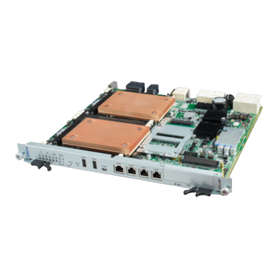
Chapter 1 Product Overview This chapter briefly describes the MIC-5332. - Page 11 With four DDR3 DIMMs per socket in a quad channel design running up to 1600MT/s, the MIC-5332 not only offers superior memory bandwidth over 3-channel designs, but can also support memory densities up 256GB using latest LR DIMM technology.
- Page 12 FMM. Please contact Advantech for more information on available RTMs. An on-board FPGA design facilitates customer-specific modifications, and the core board design can be modified or adapted to other form factors through Advantech’s DMS customization services. Figure 1.1 MIC-5332 Overview (Top Side)
-
Page 13: Block Diagram
1.2 Block Diagram The hardware implementation is shown in the following block diagram. Refer to Table 1.1 (next page) for the detailed product technical specification. : Option Figure 1.2 MIC-5332 Block Diagram... -
Page 14: Product Configurations
Dual 10GE Module with 2x SFP+ front IO based on i82599ES FMM-5002E Server Graphics Module with external VGA Port FMM-5006E MIC-5332 QuickAssist Accelerator FMM Table 1.2 MIC-5332 Related Products Note: Contact Advantech for information on available and future RTMs and FMMs. -
Page 15: Board Features
Chapter 2 Board Features This chapter describes the MIC-5332 hardware features. -
Page 16: Technical Data
WindRiver PNE/LE 4.2, RedHat Enterprise 5.7 & 6.2, CentOS 6.1, System Windows Server 2008 BMC Controller NXP LPC1768 (Cortex M) IPMC IPMI Compliant with IPMI 1.5 using Advantech IPMI code base Supervision 1 for x86 BIOS POST, OS Boot, Application Watchdog Timer Interval IPMI compliant Site... -
Page 17: Product Features
2.2 Product Features 2.2.1 Processors The MIC-5332 supports dual Intel® Xeon® E5-2600 series processors, using latest 32nm silicon architectures with built-in memory controller. It is a two-chip platform (CPU and PCH) as opposed to traditional three-chip platforms (CPU, MCH and IOH). -
Page 18: Platform Controller Hub (Pch)
Intel® Xeon® E5-2600 series processors support 40 PCI Express Gen3 ports. They are configured to two x16 ports, one x8 port and five x4 ports in the MIC-5332. The PCI Express interface is connected to RTM (Port1 and 2) and update channel (Port 3, optional). - Page 19 (Device 31: Function 5) will be disabled. Please contact your Advantech technical support team for more detail information. In the MIC-5332, SATA 6 Gbps support is available on PCH Ports 0 and 1 only, and reserved for onboard storage modules like CFast or 2.5” SSD. For detailed configurations, please refer to table 2.4:...
-
Page 20: Usb Controller
Table 2.4 SATA Port Configuration on the MIC-5332 The MIC-5332 is also able to support SAS devices. 4 SAS 2.0 channels are reserved for SAS or SATA devices on RTM boards. For details, please see table 2.5. Port No. Speed... - Page 21 MIC-5332 are listed as table 2.7. Figure 2.2 DIMM slots on the MIC-5332 DIMM Type RDIMMs UDIMMs LRDIMMs 2GB, 4GB, 8GB, 16GB and 2GB, 4GB and 8GB Size 8GB, 16GB and 32GB 32GB Speed 1066 / 1333 / 1600 1066 / 1333...
-
Page 22: Ethernet Interface
Memory for further details. 2.4 Ethernet Interface 2.4.1 Base Interface The MIC-5332 uses Intel® i350-AM4 LAN controller, connected to the Intel® Xeon® E5-2600 series Processor (CPU0) through a PCIe x4 interface to provide dual GbE ports for the Base Interface. -
Page 23: Fabric Interface
The MIC-5332 Fabric Interface supports PICMG 3.1 Options 1 or 9. 2.4.3 I/O Ethernet Interface There are three I/O LAN ports on the MIC-5332 front panel, which are implemented using Intel® i350-AM4 quad port GbE controller and 82579 gigabit Ethernet PHY (MAC provided by C604 PCH). - Page 24 Copper 10/100/1000 Mb/s Table 2.8: Ethernet Interface Link Speed Configuration 2.5 Zone 3 Interface (RTM) The MIC-5332 supports the following connectivity to an optional RTM through the zone 3 interface (please refer to the Appendix D, Zone3 interface (RTM) pin-out):...
- Page 25 RTM board. It is managed by the main board’s IPMC or RTM board’s MMC, but does not support the hot-swap function. Customers may request a customized FMM (please contact your Advantech representative) or choose from the following Advantech FMM-5000 options. For detailed specifications, please refer to table 2.10.
-
Page 26: Installation
Chapter 3 Installation This chapter describes the procedure to install the MIC-5332 into a chassis. Peripherals (DIMMs, SSD) installation, jumper setting and LED definition are also described here. -
Page 27: Memory Installation
3.1 Processor The MIC-5332 is shipped with two CPUs and heat sinks installed. Please do not attempt to remove the heat sinks, or the cooling performance will be affected. Tampering with the heat sinks will result in loss of warranty. - Page 28 SOL, where an input character is received. For example, when a RJ45 to DB9 cable is plugged into the MIC-5332, by detecting a character entered through the cable, the UART multiplexer will automatically bridge...
- Page 29 connected and the user enters any character, the multiplexer will then switch the output to this interface as this is the latest request. The previous RJ45 link will consequently become disconnected. RJ45 miniUSB UART UART1 Zone3 UART2 Step1. User establishes the console link through any available output (e.g.
- Page 30 RJ45 miniUSB UART UART1 Zone3 UART2 Step2. When the user plugs another console cable into the MIC-5332, (e.g. miniUSB), the UART MUX will switch the output from RJ45 to this new interface (last in, first serve rule)
- Page 31 For a terminal PC to connect to the console function on the MIC-5322 with a RJ45 to DB9 cable, no additional driver is needed. Prerequisite: RJ45 to DB9 cable mini-USB (COM2) The MIC-5332 uses a USB-to-UART bridge called CP2102-GM from Silicon Labs® to...
-
Page 32: Terminal Emulator
USB 2.0 full-speed function controller, bridge control logic, and a UART interface with transmit/receive buffers and modem handshake signals. For a terminal PC to connect to the console function on the MIC-5332 with a mini-USB to USB cable, the CP2102 driver is available for download from Silicon Labs® website (hyperlink below), and must be installed on the terminal PC. -
Page 33: Putty Configuration
3.3.3 PuTTY Configuration Assuming both the CP2102 driver and PuTTY have been installed successfully on the terminal PC with Microsoft Windows, the user can check the COM port (UART) number under “COM and LPT” in the “Device Manager”, which can be accessed by entering the “Control Panel”... - Page 34 Figure 3.3b PuTTY Configurations If the connection is successful and the user enters BIOS setup menu, upon boot the MIC-5332 BIOS setup menu will be displayed on the PuTTY screen. Figure 3.4 MIC-5332 BIOS setup menu shown on PuTTY screen...
- Page 35 2. Choose a node slot in chassis, and align the PCB edge to the card guide rail. 3. Carefully slide the MIC-5332 into the system until the connector contacts start to mate into the backplane. Make sure the front panel alignment pin falls into the receptacle.
- Page 36 Note: Regarding the slot information, please refer to the backplane/chassis manual The MIC-5332 also supports hot-swap, i.e. no need to turn off the chassis power before installing the board. To extract the MIC-5332 from the chassis: 1. Unlock the ejector handle at the bottom side, next to the FMM bay.
- Page 37 Insert the FMM module until the connector is firmly seated in the socket. Install the screws (refer to figure 3.10), and power on the MIC-5332 to make sure the installation is completed. To remove the FMM, follow the procedure in reverse.
- Page 38 Bracket Module Figure 3.8 MIC-5332 w/ FMM module and SSD Bracket locations Locate the FMM site on the blade Figure 3.9...
-
Page 39: Front Panel
Solid State Drive (SSD) or CFast cards are available to be installed on the MIC-5332. The MIC-5332 can support one 2.5” SSD, or two CFast cards. It is an option by customer request, and the MIC-5332 will need to be installed with a specific daughter board and bracket from the factory. -
Page 40: Led Definition
For details, please contact your Advantech representative to obtain further support. Retaining Thumbscrews FI Channel 1/2 Status LEDs Handle (Top side) BI Channel1/2 Status LEDs SAS Status LEDs OOS LED Dual Color User LEDs Health LED Button2 (Reserved) Button1 (Reserved) - Page 41 Display Status Bright … Blink Table 3.2 LED Signal Identification LED Name Function Display 10Gb/s Link … 10Gb/s Active Speed/Link/ FI port 1/2/3/4 1Gb/s Link Active … 1G Active No Link 1Gb/s BI port 1/2 100Mb/s Speed 10Mb/s BI Port 1/2 Link BI port 1/2 …...
-
Page 42: Jumper Settings
FI channel 3 and 4 support is optional and only active when populating with the FMM-5001BE on the FMM site of the MIC-5332. 3.4.7 Jumper Settings This section describes the jumpers on the MIC-5332 for reference. In normal operation, users are not to access or modify jumpers. Jumper... - Page 43 Figure 3.10 Jumper Locations...
-
Page 44: Hardware Management
Chapter 4 Hardware Management This chapter describes the IPMC firmware features. -
Page 45: Intelligent Platform Management Controller
It provides extension interfaces with configurable routing options as well as some additional stand-alone functionality. One of the very basic benefits of Advantech IPMI Core G02 is the high level of flexibility. Its modular structure allows the same firmware core to be... - Page 46 Figure 4.1 IPMC Interface Block Diagram 4.2.1.1 IPMB-0 Interface The IPMB0 interface is the communication path between the ShMC and IPMC through Zone 1. Two–way redundant IPMB-0 channels (IPMB0-A and IPMB0-B) provide immunity against failures of one of IPMB-0 channels. For a request received over IPMB0-A, the response will be sent over IPMB0-B.
- Page 47 Note: The IPMC firmware provides an OEM IPMI command to allow users to switch the IMPC/FPGA connected NC-SI interface between the front panel LAN IO and the Base interface LAN controllers and also to select between the 2 IO and BI connections. See below the description of the corresponding OEM commands: LAN controller interface selection The BMC firmware provides an OEM IPMI command to allow users to switch the BMC...
-
Page 48: System Event Log (Sel)
LAN channel selection priority setting list: 0 = The first channel that links up, gets the NC-SI connection to the BMC. 1 = Channel 1 is the preferred port if it is up, otherwise use channel 2 if it is up. 2 = Channel 2 is the preferred port if it is up, otherwise use channel 1 if it is up. -
Page 49: Field Description
(Based on manufacturing date) Board manufacturer type/length 0xC9 Board manufacturer Advantech Board product name type/length 0xC8 Board product name MIC-5332 Board serial number type/length 0xCA Board serial number (10 characters, written during manufacturing) Board part number type/length 0xC8 Board part number... - Page 50 Moreover, the IPMC Management Subsystem also registers the below logical sensors: PICMG Hot Swap sensors PICMG IPMB sensor BMC Watchdog Version change OEM Sensor: Integrity Sensor Here under please find the complete list of all contained sensor data records contained in the IPMC sensor repository MIC-5332:...
- Page 51 Sensor Name Description FRU Device Locator IPMI FRU Device Locator HOTSWAP PICMG Frontboard Hotswap sensor HS_RTM PICMG RTM Hotswap sensor BMC_WATCHDOG IPMI Watchdog 2 sensor FW_PROGRESS IPMI FW Progress sensor VERSION_CHANGE IPMI Version Change sensor IPMB_0 PICMG IPMB-0 status sensor VR_HOT Discrete sensor Voltage regulator Status PROC_HOT...
-
Page 52: Voltage Sensors
CPU1_CORE-VOL Threshold sensor CPU-1 Core Voltage CPU1_1_80-VOL Threshold sensor CPU-1 1.80V DDR_AB-VOL Threshold sensor DDR Voltage 1.5V DDR_CD-VOL Threshold sensor DDR Voltage 1.5V DDR_EF-VOL Threshold sensor DDR Voltage 1.5V DDR_GH-VOL Threshold sensor DDR Voltage 1.5V V48-TMP Threshold sensor DC/DC converter temperature INTAKE0-TMP Threshold sensor LM75 intake temperature POWER-TMP... -
Page 53: Thermal Sensors
1.25 1.30 1.57 1.65 1.97 Table 4.4 MIC-5332 Voltage Sensors List 4.3.2 Thermal Sensors Board temperatures are monitored by the NuvoTon NCT7904D, TI TMP75 and TI LM86 voltage sensors. One TMP75 (with ±2℃ accuracy) is located in the air inlet... - Page 54 RTMLink. The FPGA asserts OC#[11:8] to the PCH for alerting. 4.3.2.1 Threshold (Temperature) The MIC-5332 supports TI TMP75 and NI LM86 as temperature sensors. When the temperature is crossing a threshold, the event will not only be logged, but the shelf manager will also adjust the system fan speed accordingly..
- Page 55 4.3.3 Discrete sensors 4.3.3.1 IPMC Device Locator Each IPMC provides a PICMG compliant FRU device locator for the subsystem. This record is used to hold location and type information of the IPMC. 4.3.3.2 Mezzanine Module Device Locator The FRU device locator for each Add-In card is also placed in the front board sensor data repository.
- Page 56 The event message of the integrity sensor contains three bytes of data. Byte 1 is the IPMI header, which is a fixed value A0. Byte 2 satisfies the component, while byte 3 stands for its action. Table 4.8 shows the supported event code structure generated by the integrity sensors on the MIC-5332: Component Action...
-
Page 57: Watchdog Timers
(BMC watchdog). When the IPMC is firmware is stuck, the IPMC watchdog bites and resets the IPMC. The payload is not affected from this watchdog event. The BMC Watchdog of the MIC-5332 IPMC is used for: BIOS Power On Self Test (POST) watchdog... -
Page 58: Serial-Over-Lan (Sol)
Verify fabric compatibility 4.5.1 Zone3 (RTM) The IPMC on the MIC-5332 and the MMC on the RTM handle the E-keying control. For the RTM, the PCI Express ports need E-keying to carry out the hot swap function. Brief E-keying information of the zone 3 is listed in Table 4.10. The user may also get a detailed E-keying connectivity record via a CLI command through the shelf manager. - Page 59 console communication with the payload over a LAN interface (See Section 4.2.1.4, NC-SI Interface). The SoL function is available for I/O LAN (LAN1 & LAN2) and the Base Interface, but not simultaneously. Each of these two interfaces uses the Intel quad port LAN controller Intel i350-AM4, and supports the failover mechanism: As one channel in use is unexpectedly disconnected from the network, the IPMC will switch and re-establish the SoL session to the other channel within the same LAN...
- Page 60 3. Choose a proper connection (LAN, KCS, or IPMB) to the MIC-5332. Taking LAN for example, connect theFront Panel IO GbE-LAN RJ-45 port (LAN1 or LAN2) to the LAN port on a PC via an Ethernet cable. 4. Turn on the MIC-5332.
- Page 61 LAN. With the help of SOL, user can connect to a virtual serial console (e.g. payload x86 system) from remote. SOL can be used on MIC-5332 for serial-based OS and pre-OS communication over LAN (e.g. OS command-line interface and serial redirected BIOS menu).
- Page 62 Username: "administrator" Password: "advantech" <2> LAN Configuration with IPMItool The open source IPMItool utility is used in this chapter for the MIC-5332 SOL and LAN parameter configuration. Any other utility, based on standard IPMI commands, can be used as well.
- Page 63 To get an overview of all possible commands within an IPMItool command group, please use the single keywords (e.g. “lan”, “user” or “sol”) only. <2.1> LAN Commands - lan print [channel number] Get the LAN configuration parameters for a given channel. [root@localhost ~]# ipmitool lan print Set in Progress : Set Complete...
- Page 64 <3> SOL Session with IPMItool Advantech recommends using IPMItool to successful open a SOL session with MIC-5332. The “lanplus” interface (RMCP+) of IPMItool must be used to be able to change SOL parameters and establish SOL sessions. Following general IPMItool parameters are needed for RMCP+ and IPMItool “sol”...
- Page 65 User account, default “administrator” -P <Password> Password used with specified user account (default password for user “administrator” is “advantech”) <3.1> SOL Parameter Commands - sol info [channel number] Read out the SOL configuration parameters for a given channel. # ipmitool -I lanplus <IP-Address> -U <User> -P <Password> sol info...
- Page 66 | 9.6 | 19.2 | 38.4 | 57.6 | 115.2 <3.2> SOL session activation Finally, the IPMItool “sol activate” command need to be issued to establish the SOL session to MIC-5332 from remote. # ipmitool -I lanplus <IP-Address> -U <User> -P <Password> sol activate [SOL Session operational.
- Page 67 “ipmitool raw 0x2e 0x40 0x39 0x28 0x00 0x06 0x00 0x00”. 4.8 MAC Address Mirroring All MAC addresses consumed by the MIC-5332 will also be stored in the FRU EEPROM, making them available to be read even if the payload is not powered. User...
-
Page 68: Rtc Synchronization
Net function 0x2E / 0x2F (OEM) <Command> 0xe2 <IANA ID> Advantech IANA ID = 0x39 28 00 <MAC address no> 0x00 for Fabric Interface Channel 0 0x01 for Fabric Interface Channel 1 0x02 for Base Interface Channel 0 0x03 for Base Interface Channel 1... - Page 69 Figure 4.4 Real Time Clock Synchronization Overview From IPMC’s point of view are two more participants in an ATCA System, which maintain their own time, because they implement a separate Real-Time-Clock. These are the Shelf Manager and the on-board payload. The IPMC firmware has implemented a RTC synchronization feature, which allows configuring the RTC synchronization between Shelf Manager, IPMC and payload according to the need of each user.
- Page 70 Chapter 5 AMI APTIO BIOS Setup This chapter describes how to configure the AMI APTIO BIOS (UEFI BIOS).
-
Page 71: Entering Setup
This section describes the AMI APTIO BIOS, UEFI compliant, which has been specifically adapted to the MIC-5332. With the AMI APTIO BIOS Setup program, users can modify BIOS settings and control the special features of the MIC-5332. The setup program uses a number of menus for making changes and turning special features on or off. -
Page 72: Main Setup
showing basic BIOS and blade information.Press <DEL> or <F2> and users will immediately be allowed to enter Setup. Figure 5.2 Press <DEL> or <F2> to run setup 5.3 Main Setup When users first enter the BIOS Setup Utility, users will enter the Main setup screen. Users can always return to the Main setup screen by selecting the Main tab. -
Page 73: System Time/System Date
MM/DD/YY format. The time is entered in HH:MM:SS format. 5.4 Advanced BIOS Features Setup Select the Advanced tab from the MIC-5332 setup screen to enter the Advanced BIOS Setup screen. Users can select any of the items in the left frame of the screen, such as CPU Configuration, to go to the sub menu for that item. - Page 74 Figure 5.3 Advanced BIOS Features Setup Snapshot Feature Default Description Enable or Disable Boot Option for Legacy Launch PXE OpROM Disabled Network Devices Enabled Enable or Disable Boot Option for Legacy Mass Launch Storage OpROM Storage Devices with Option ROM PCI Subsystem Settings Submenu PCI, PCI-X and PCI Express Settings...
-
Page 75: Pci Subsystem Settings
5.4.1 PCI Subsystem Settings Figure 5.4 PCI Subsystem Settings Feature Default Description PCI Bus Driver Version Display only Show current PCI bus driver version In case of multiple Option ROMs (Legacy and PCI ROM Priority Compatible EFI Compatible), specifies what PCI Option ROM to launch. -
Page 76: Acpi Settings
5.4.2 ACPI Settings Figure 5.5 ACPI Settings Feature Default Description Enables Disables BIOS ACPI Auto Enable ACPI Auto Conf Disabled Configuration. Enables or Disables System ability to Hibernate Enable Hibernation Enabled (OS/S4 Sleep State). This option may be not effective with some OS. Select the highest ACPI sleep state the system S3 (Suspend ACPI Sleep State... -
Page 77: Whea Configuration
Figure 5.6 Trusted Computing Feature Default Description Enables or Disables BIOS support for security device. O.S. will not show Security Device. TCG Enabled Security Device Sup EFI protocol and INT1A interface will not be available. Enable/Disable Security Device. NOTE: Your TPM State Disabled Computer will reboot during restart in order to... -
Page 78: Cpu Configuration
Figure 5.7 WHEA Configuration 5.4.5 CPU Configuration Figure 5.8 CPU Configuration Feature Default Description Socket 0 CPU Information Display Only Socket specific CPU Information Socket 1 CPU Information Display Only Socket specific CPU Information CPU Speed Display Only Show the current CPU speed in use... -
Page 79: Cpu Power Management Configuration
Show if the current CPU supports 64-bit or 64-bit Display Only Enabled for Windows XP and Linux (OS optimized for HT Technology) and Disabled Hyper-threading Enabled for other OS (OS not optimized for Hyper-Threading Technology). When Disabled only one. Number of cores to enable in each processor Active Processor Core package. -
Page 80: Sata Configuration
User can enable or disable the runtime error logging support via a sub option of the advanced setting (default is disabled). Figure 5.9 Runtime Error Logging 5.4.7 SATA Configuration Figure 5.10 SATA Configuration... -
Page 81: Sas Configuration
Aggressive Link Power Management Support. Table 5.7 SATA Configuration The MIC-5332 supports total 6 SATA devices (details, please refer to section 2.2.6). Users can check the status each by each via this sub option. Also users can select the proper SATA mode to guide the operation system when SATA devices are plugged on the MIC5332. - Page 82 The MIC-5332 supports USB Plug & Play, PnP. That is, users can find all USB devices which are plugged on the MIC-5332. They can configure the parameters to enhance the USB device performance, such as mass storage devices. Figure 5.12 USB Configuration...
-
Page 83: Serial Port Console Redirection
Figure 5.13 UART MUX Configuration 5.4.11 Serial Port Console Redirection The MIC-5332 has two COM ports that are integrated on the front panel. One is COM1 through the RJ45 connector, and another is COM2 through the miniUSB connector. Users can configure the related parameters of these two serial port consoles in this submenu. -
Page 84: Network Stack
The settings specify how the host computer and the remote computer (which the user is Console Redirection Settings Submenu using) will exchange data. Both computers should have the same or compatible settings. Table 5.9 Serial Port Console Redirection Figure 5.14 Serial Port Console Redirection 5.4.12 Network Stack Users can enable or disable the network stack (PXe and UEFI) via this submenu (default is disable Link). -
Page 85: Main Configuration Page
This function allows users to give a worldwide unique name for the iSCSI initiator. Figure 5.16 iSCSI Initiator 5.4.14 Main Configuration Page The MIC-5332 supports five MACs (four from the Intel i350, one from the PCH). Users can configure legacy boot protocol, link speed and Wake On LAN for each of them. -
Page 86: Chipset Setup
Figure 5.17 Main Configuration Page 5.5 Chipset Setup Select the chipset tab from the MIC-5332 setup screen to enter the Chipset Setup screen. Users can configure the parameters of north bridge (CPU), south bridge (PCH) and ME system (display only), respectively. -
Page 87: North Bridge
Users can set up all parameters related to the IOH function in the North Bridge page. Moreover, the MIC-5332 BIOS allows users to configure the PCIe link speed (gen1, gen2 or gen3) and its functions visible (x16, x8x8, x8x4x4, x4x4x8 or x4x4x4x4) in the IOH configuration submenu. -
Page 88: South Bridge
5.5.2 South Bridge Users can set up all parameters related to the PCH function in the South Bridge page. Also, users can configure (to enable or disable) eight USB 2.0 channels supported on the MIC-5332 in this page. Feature Default... - Page 89 Disable SCU devices Disabled Enable/Disable Patsburg SCU Devices. Enable/Disable onboard SAS Option rom Onboard SAS Oprom Disabled Launch Storage OpROM is enabled. Enable/Disable onboard SATA RAID Option rom Onboard SATA RAID Opr Enabled if Launch Storage OpROM is enabled. High Precision Timer Enabled Enable/Disable the High Precision Event Timer.
- Page 90 5.6 Server Management (Mgmt) Setup Users can configure the watchdog timer both for the FRB-2 and OS Wtd in the server mgmt page. For details of the BMC self test log and system event log, users can decide to enable the function to record the logs, or erase the logs through BMC self test log submenu, or the system event log submenu.
-
Page 91: Boot Setup
Logs the report returned by the BMC self test BMC self test log Submenu command. Press <Enter> to change the SEL event log System Event Log Submenu configuration. View FRU information Display Only Press <Enter> to view FRU information. Table 5.12 Server Mgmt Configuration 5.7 Boot Setup Users can configure the system boot priority settings via the boot page. -
Page 92: Security Setup
Enables disables boot with initialization of a minimal set of devices Fast Boot Disabled required to launch active boot option. Has no effect for BBS boot option. CSM16 Module Version Display Only Shows the current version in use. Option ROM Messages Force BIOS Set display mode for Option ROM. - Page 93 Maximum length: 20 5.9 Save & Exit Option The MIC-5332 BIOS allows users to store BIOS configuration results as “User Defaults.” Users can select “Save as User Defaults” to record all changes which had been made in previous pages as the default setting for further use.
- Page 94 Restore Defaults Restore/Load Default values for all the setup options. Save as User Defaults Save the changes done so far as User Defaults. Restores User Defaults Restore the User Defaults to all the setup options. Table 5.14 Save & Exit Configuration...
-
Page 95: Firmware Upgrade
Chapter 6 Firmware Upgrade This chapter describes how to update the IPMC FW, FPGA and BIOS for the MIC-5332. - Page 96 6.1 HPM.1 Upgrade Functionality All firmware updates/upgrades (IPMC firmware, FPGA configuration and BIOS SPI Flash) can be performed through HPM.1 over IPMI. Please follow the procedures described in the following sections. 6.2 IPMItool Before upgrading, users need to prepare an update utility called “IPMItool” or any other HPM.1 compliant upgrade agent.
- Page 97 [root@localhost ~]#ipmitool hpm upgrade mic5332_standard_hpm_fw_00_46.img PICMG HPM.1 Upgrade Agent 1.0.2: Validating firmware image integrity...OK Performing preparation stage... Target Product ID : 21298 Target Manufacturer ID: 10297 Performing upgrade stage: ------------------------------------------------------------------------------- |ID | Name Versions Upload Progress | Upload| Image | | Active| Backup| File 100%| Time | Size...
-
Page 98: Fpga Upgrade
6.3.2 Activate HPM FW image Although the new IPMC FW is successfully downloaded to the board (called “deferred” version), it needs to be activated before it will be functional. Use following HPM.1 command: [root@localhost ~]# ipmitool hpm activate PICMG HPM.1 Upgrade Agent 1.0.2: Waiting firmware activation...OK During the FW update the front panel FRU LED’s 1 and 2 (red OOS and green payload LED) are flashing! This procedure needs around 30 seconds to finalize... - Page 99 [root@localhost ~]#ipmitool hpm upgrade mic5332_standard_hpm_fpga_02_14.img PICMG HPM.1 Upgrade Agent 1.0.2: Validating firmware image integrity...OK Performing preparation stage... Target Product ID : 21298 Target Manufacturer ID: 10297 Performing upgrade stage: ------------------------------------------------------------------------------- |ID | Name Versions Upload Progress | Upload| Image | | Active| Backup| File 100%| Time | Size...
- Page 100 6.4.2 Activate HPM FPGA image Although the new FPGA is successfully downloaded to the board (called “deferred” version), it needs to be activated before it will be functional. Use following HPM.1 command: [root@localhost ~]# $ ipmitool hpm activate PICMG HPM.1 Upgrade Agent 1.0.2: 6.4.3 Payload Reset In order to activate the new FPGA image a payload reset is required.
-
Page 101: Bios Upgrade
-------Target Information------- Device Id : 0x22 Device Revision : 0x81 Product Id : 0x5332 Manufacturer Id : 0x2839 (Advantech) --------------------------------- |ID | Name Versions | Active| Backup| --------------------------------- | 0 |5332 BL 0.45 | --.-- | | 1 |5332 IPMC 0.45 |... - Page 102 6.5.1 Upload new BIOS image Type IPMItool HPM.1 upgrade command and select the new BIOS image. [root@localhost ~]# ipmitool hpm upgrade mic5332_standard_hpm_bios_00_23.img PICMG HPM.1 Upgrade Agent 1.0.2: Validating firmware image integrity...OK Performing preparation stage... Target Product ID : 21298 Target Manufacturer ID: 10297 Performing upgrade stage: -------------------------------------------------------------------------------...
- Page 103 [root@localhost ~]# $ ipmitool hpm activate PICMG HPM.1 Upgrade Agent 1.0.2: 6.5.3 Payload Reset In order to activate the new BIOS image a payload reset is required. (*) Component requires Payload Cold Reset The payload reset can be performed through different ways. If the user is working on the OS via KCS a linux “reboot”,”poweroff”...
- Page 104 -------Target Information------- Device Id : 0x22 Device Revision : 0x81 Product Id : 0x5332 Manufacturer Id : 0x2839 (Advantech) --------------------------------- |ID | Name Versions | Active| Backup| --------------------------------- 6.6 NVRAM Upgrade In contrast to the BIOS image update, the setting update image is not directly written to any of the BIOS SPI flashes.
- Page 105 [root@localhost ~]# ipmitool raw 0x2E 0x40 0x39 0x28 0x00 0x03 0x01 <section> ...
- Page 106 6.6.2 Upload new NVRAM image Type IPMItool HPM.1 upgrade command and select the new NVRAM image. [root@localhost ~]# ipmitool hpm upgrade mic5332_standard_hpm_bios_00_05.img PICMG HPM.1 Upgrade Agent 1.0.2: Validating firmware image integrity...OK Performing preparation stage... Target Product ID : 21298 Target Manufacturer ID: 10297 Performing upgrade stage: -------------------------------------------------------------------------------...
- Page 107 6.6.4 Payload Reset In order to activate the new NVRAM image a payload reset is required. (*) Component requires Payload Cold Reset The payload reset can be performed through different ways. If the user is working on the OS via KCS a linux “reboot”,”poweroff” or “halt” will activate the new NVRAM image.
- Page 108 Appendix A IPMI/PICMG Command Subset Supported by IPMC...
- Page 109 IPM Device “Global” Commands IPMI IPMI / PICMG3.0 / AMC2.0 Command NetFn Spec Ref Requirement Get Device ID 20.1 Mandatory Cold Reset 20.2 Optional Warm Reset 20.3 Optional Get Self Test Results 20.4 Mandatory Get Device GUID 20.8 Optional Broadcast “Get Device ID 20.9 Mandatory BMC Watchdog Timer Commands...
- Page 110 Set User Access 22.26 Optional Get User Access 22.27 Optional Set User Name 22.28 Optional Get User Name 22.29 Optional Set User Password 22.30 Optional Activate Payload 24.1 None Deactivate Payload 24.2 None Set User Payload Access 24.6 None Get User Payload Access 24.7 None Get Channel Payload Support...
- Page 111 Get Sensor Reading 35.14 Mandatory Get Sensor Type 35.16 Optional FRU Device Commands IPMI IPMI / PICMG3.0 / AMC2.0 Command NetFn Spec Ref Requirement Get FRU Inventory Area Info 34.1 Storage Mandatory Read FRU Data 34.2 Storage Mandatory Write FRU Data 34.3 Storage Mandatory...
- Page 112 AdvancedTCA® Commands PICMG® IPMI / PICMG3.0 / AMC2.0 Command NetFn 3.0 Table Requirement Get PICMG Properties 3-11 PICMG Mandatory Get Address Info 3-10 PICMG Mandatory FRU Control 3-27 PICMG Mandatory Get FRU LED Properties 3-29 PICMG Mandatory Get LED Color Capabilities 3-30 PICMG Mandatory...
- Page 113 2Eh, 2Fh A.1 IPMItool raw command To be able to use the Advantech OEM commands with the open source IPMItool, users have to employ the “raw” command of IPMItool. Please find below command structure details of the IPMItool raw command.
- Page 114 A.2.1 LAN controller interface selection The MMC firmware provides an OEM IPMI command to allow users to switch the MMC connected NC-SI interface between one front panel LAN IO RJ-45 connector and the Base interface. These commands can be used to read out the actual selected IPMI-over-LAN / Serial-over-LAN interface and to change the selection.
- Page 115 39 28 00 A.2.3 FPGA COM port UART MUX MIC-5332 implements several serial interfaces, which can be configured in some ways. This is done inside the FPGA with the help of an UART MUX (refer to chapter <x.x.x – UART MUX>). The BMC provides OEM commands to configure these UARTs via IPMI.
- Page 116 0x02 Front Panel RJ45 0x03 Front panel mini-USB (default) 0x04 RTM mini-USB 0x05 RTM RJ45 0x0F Automatic mode Table 2: COM1 UART MUX settings COM2 MUX: Setting Connection 0x00 no interface connected, open 0x01 Serial-over-LAN (SOL) 0x02 Front Panel RJ45 0x03 Front panel mini-USB (default) 0x04...
- Page 117 The blade LAN Controller MAC addresses will also be stored in the FRU EEPROM, making the MAC’s available even if the payload is not powered. The MIC-5332 board is equipped with 7 MAC addresses in total. Please find below the used order in the FRU EEPROM Internal Use Area:...
- Page 118 PCH MAC IPMC MAC 8..x FMM MAC addresses (if plugged) Table 4: MAC Address mapping table Read MAC Address OEM command: ipmitool raw 0x2e 0xe2 0x39 0x28 0x00 <MAC Number> Response: 39 28 00 <MAC-Address> A.6 Load Default Configuration OEM command Several configurations settings are provided by the IPMC (verify chapter <x.x.x Configuration Setting OEM commands>).
- Page 119 Appendix B Zone 1 P10 Pin-out pin name Pin use Reserved No connected Reserved No connected Reserved No connected Reserved No connected Hardware Address bit 0 Hardware Address bit 1 Hardware Address bit 2 Hardware Address bit 3 Hardware Address bit 4 Hardware Address bit 5 Hardware Address bit 6 HA7/P...
- Page 120 -48V_A -48V input feed A -48V_B -48V input feed B...
- Page 121 Appendix C Zone 2 Interface pin-out Zone 2 J20 pin out – Update Channel N.C. N.C. N.C. N.C. N.C. N.C. N.C. N.C. Tx4(UP)+ Tx4(UP)‐ Rx4(UP)+ Rx4(UP)‐ N.C. N.C. N.C. N.C. Tx2(UP)+ Tx2(UP)‐ Rx2(UP)+ Rx2(UP)‐ Tx3(UP)+ Tx3(UP)‐ Rx3(UP)+ Rx3(UP)‐ Tx0(UP)+ Tx0(UP)‐ Rx0(UP)+ Rx0(UP)‐ Tx1(UP)+ Tx1(UP)‐ Rx1(UP)+ Rx1(UP)‐ N.C. ...
- Page 122 Zone 2 J22 pin out – Base Interface and Fabric Interface N.C. N.C. N.C. N.C. N.C. N.C. N.C. N.C. N.C. N.C. N.C. N.C. N.C. N.C. N.C. N.C. N.C. N.C. N.C. N.C. N.C. N.C. N.C. N.C. N.C. N.C. N.C. N.C. N.C. N.C. ...
- Page 123 Zone 2 J23 pin out – Base Interface and Fabric Interface Pin A B C D E F G H FI_CH2 FI_CH2 FI_CH2 FI_CH2 FI_CH2 FI_CH2 FI_CH2 FI_CH2 Tx2+ Tx2‐ Rx2+ Rx2‐ Tx3+ Tx3‐ Rx3+ Rx3‐ FI_CH2 FI_CH2 FI_CH2 FI_CH2 FI_CH2 FI_CH2 FI_CH2 ...
- Page 124 Appendix D Zone 3 Interface (RTM) pin-out Zone 3 J31 pin out RTM_+12V RTM_3.3V_MP RTM_IPMBL RTM_ENABLE RTM_LINK RTM_MMC_ RTM_PERST0# RTM_PS# not connected not connected RTM_USB1 RTM_USB0 not connected not connected RTM_UART1 RTM_UART0 not connected RTM_PCIE2_CLK RTM_PCIE1_CLK RTM_PCIE0_CLK PEx4_2: RTM_PE4‐0_3 PEx4_2: RTM_PE4‐0_2 PEx4_2: RTM_PE4‐0_1 PEx4_2: RTM_PE4‐0_0...
- Page 125 Zone 3 J32 pin out not connected not connected RTM_USB3 RTM_USB2 TCLKD TCLKC TCLKB TCLKA not connected not connected not connected not connected not connected not connected SATA1: RTM_SATA1 SATA1: RTM_SATA0 SAS0: RTM_SAS3 SAS0: RTM_SAS2 SAS0: RTM_SAS1 SAS0: RTM_SAS0 Zone 3 J34 pin out PEx16_1: PEx16_1: PEx16_1: PEx16_1: RTM_PE16‐1_0 RTM_PE16‐1_4 RTM_PE16‐1_0 RTM_PE16‐1_4 RX RX TX ...
- Page 126 PEx16_1: PEx16_1: PEx16_1: PEx16_1: RTM_PE16‐1_10 RTM_PE16‐1_14 RTM_PE16‐1_10 RTM_PE16‐1_14 RX RX TX TX PEx16_1: PEx16_1: PEx16_1: PEx16_1: RTM_PE16‐1_3 RTM_PE16‐1_7 RTM_PE16‐1_3 RTM_PE16‐1_7 RX RX TX TX PEx16_1: PEx16_1: PEx16_1: PEx16_1: RTM_PE16‐1_11 RTM_PE16‐1_15 RTM_PE16‐1_11 RTM_PE16‐1_15 RX RX TX TX ...
- Page 127 Appendix E FMM Interface pin-out 1 NC FM_PRSNT# 2 GND FI3_RX0_P PCIE1_TX0_P 3 GND FI3_RX0_N PCIE1_TX0_N 4 NC FI3_RX1_P PCIE1_TX1_P 5 NC FI3_RX1_N PCIE1_TX1_N 6 GND FI3_RX2_P PCIE1_TX2_P 7 GND FI3_RX2_N PCIE1_TX2_N 8 NC FI3_RX3_P PCIE1_TX3_P 9 NC FI3_RX3_N PCIE1_TX3_N 10 GND FI4_RX0_P PCIE1_TX4_P...
- Page 128 33 FPGA_GPIO_N7 GND PCIE0_RX7_N PCIE1_RX7_N 34 GND PCIE0_REF_CLK_P GND PCIE1_REF_CLK_P 35 GND PCIE0_REF_CLK_P GND PCIE1_REF_CLK_P 36 NC #FI3_LED_HS SAS_SATA0_TX_P GND 37 NC #FI3_LED_LS RST# SAS_SATA0_TX_N SAS_SATA0_RX_P 38 GND 3.3V_SB I2C_SCL SAS_SATA0_RX_N 39 12V JTAG_EN# I2C_SDA 40 12V HPC only HPC only 1 NC 2 GND FI3_TX0_P...
- Page 129 27 GND FPGA_GPIO_N0 PCIE0_TX4_N 28 FPGA_GPIO_P2 GND PCIE0_TX5_P 29 FPGA_GPIO_N2 GND PCIE0_TX5_N 30 GND FPGA_GPIO_P4 PCIE0_TX6_P 31 GND FPGA_GPIO_N4 PCIE0_TX6_N 32 FPGA_GPIO_P6 GND PCIE0_TX7_P 33 FPGA_GPIO_N6 GND PCIE0_TX7_N 34 GND 35 GND 36 NC 37 NC 38 GND USB2_DP #FI4_LED_HS 39 USB1_DP USB2_DN #FI4_LED_LS...
Need help?
Do you have a question about the MIC-5332 and is the answer not in the manual?
Questions and answers