Table of Contents
Advertisement
Advertisement
Table of Contents

Related Manuals for Intellinet 523868


Summary of Contents for Intellinet 523868
- Page 1 Managed Layer 3 access switch user ManuaL Model 523868 INT-523868-UM-0807-01...
-
Page 3: Introduction & Fcc Warning
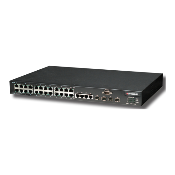
Thank you for purchasing the INTellINeT NeTWoRK SolUTIoNS Managed layer 3 ™ Access Switch, Model 523868. This is a high-performance managed SNMP switch that provides users with 24 10/100 Mbps ethernet and four Gigabit combo ports. The Web/SNMP management provides remote control capability that gives flexible network management and monitoring options. -
Page 4: Table Of Contents
tabLe of contents section page Introduction & FCC Warning ................... 3 HARdWARe ......................... 6 1.1 Front Panel Connections & Indicators ..............6 1.1.1 10/100Base-TX Ports .................. 6 1.1.2 10/1001000Base-T Ports ................6 1.1.3 SFP Slots for SFP Modules ................. 6 1.1.4 leds ...................... - Page 5 2.2.6.5 VRRP ..................21 2.2.7 Bridge ......................21 2.2.7.1 Spanning Tree ................21 2.2.7.2 link Aggregation Static .............. 23 2.2.7.3 lACP ..................24 2.2.7.4 Mirroring ..................25 2.2.7.5 Static Multicast ................25 2.2.7.6 IGMP Snooping ................. 26 2.2.7.7 Traffic Control ................27 2.2.7.8 dynamic Addresses ..............
-
Page 6: Hardware
1 hardware 1.1 front Panel connections & indicators The Managed layer 3 Access Switch utilizes ports with copper and SFP fiber port connectors functioning under ethernet/Fast ethernet/Gigabit ethernet standards. 1.1.1 10/100base-tX Ports The 10/100Base-TX ports above) support network speeds of either 10 Mbps or 100 Mbps, and can operate in half- and full-duplex transfer modes. -
Page 7: Installation
Port LED Condition Status 10/100 on (green) Port operating at 100 Mbps (copper) Port operating at below 100 Mbps on (green) Illuminated when connectors are attached Flashing (green) Data traffic passing through port No valid link established on port A 25-28 on (green) Illuminated when connectors are attached Gigabit E’net... -
Page 8: Installing The Sfp Modules And Fiber Cable
1.2.3 Installing the SFP Modules and Fiber Cable 1. Slide the selected SFP module into one of the four Gigabit SFP slots below the RS-232 port, making sure the SFP module is aligned correctly with the inside of the slot. 2. -
Page 9: Configuration Using The Console Port (Rs-232)
2.1.1 Configuration Using the Console Port (RS-232) Prior to accessing the switch’s onboard agent (software that supports SNMP — see subsection 2.1.3 below) via a network connection, first configure the switch by giving it a valid IP address, subnet mask and default gateway using an out-of-band connection or the BooTP protocol. After configuring the switch’s IP parameters, you can access the onboard configuration program from anywhere in the attached network or via the Internet by using Telnet from any computer attached to the network or by using a Web browser (Internet Explorer 4.0 or above or Netscape... -
Page 10: Configuration Using Telnet And Ssh
3. The prompt screen will display. The default login is “admin,” with no preset password (just press the “enter” key). 4. The prompt Switch> will display. For a list of main commands, type “?” and press “enter.” For a list of subcommands, type a main command (such as “list”) and press “enter.”... -
Page 11: Snmp-Based Management And Settings
3. on the Switch login: line, type the pre-set password (the factory default is “admin”). Type “?” and press the “enter” key for a list of the main commands. As shown above, the “list” command has been entered below the last main command listed. 2.1.3 snMP-based Management and settings You can manage the Managed layer 3 Access Switch with SNMP Manager software (referred to as an agent) that runs locally on the device. -
Page 12: Initial Connection To The Switch
2.1.4 initial connection to the switch The switch supports user-based security that allows you to prevent unauthorized users from accessing the switch or changing its settings. This feature requires Java Runtime environment (JRe) 5.0 Update 5, which, if not already on your computer, can be easily installed in as little time as five minutes by following these steps. -
Page 13: Web Management
After completing the installation process, the program will display the screen at right every time you enter the IP address. The default username and password are both “admin.” Click “oK” to enter the switch’s management interface. NOTE: If you still have problems accessing the hyperlink: •... -
Page 14: System
• Click “New” to create a new entry for editing to the table (temporary until “Submit” is clicked). • Click “Add” to add the new entry to the table (temporary until “Submit” is clicked). • Click “Modify” to save changes to an existing entry (temporary until “Submit” is clicked). •... -
Page 15: Physical Interface
2.2.3 Physical interface Physical Interface on the Config Menu displays Ethernet port status in real time. Two options are available: Configure the port in the fields in the Interface Configuration window; and check the results in the Runtime Status window. 2.2.3.1 Interface Configuration Port: Select the port to configure. -
Page 16: Ip Interface
2.2.4 iP interface IP Interface on the Config Menu allows users to see the Layer 3 interface status in real time and configure the interface in the following fields. Interface: Select the interface to be configured (vlan1 is used by the system). IP: This is the interface IP address Mask: This is the interface subnet mask. -
Page 17: Routing
Routing Protocol: This is the routing protocol type of the route. If it’s “connected,” the destination is on the local lAN segment connected to the interface. Destination: The destination IP address will be masked to generate an IP range as the objective IP addresses of packets to be routed. -
Page 18: Ospf
2.2.6.2.1 Basic Network RIP is: enable/disable the RIP function for all layer 3 interfaces. All active l3 interfaces will be shown on the screen, and you can then enable/disable the RIP function for each. NOTE: Click “Advanced>>” to display the other two RIP screens. 2.2.6.2.2 Passive Interfaces If an interface doesn’t need to receive and forward routing... -
Page 19: Multicast Route
Priority: Set a priority to help determine the oSPF dR and BdR for a network. Transmit Delay: Set the estimated number of seconds to wait before sending a link update packet Hello Interval: Set the number of seconds between two hello packets. - Page 20 2.2.6.4.1 IGMP This screen is for configuring the IP multicast route mode and IGMP (Internet Group Management Protocol) parameters. IP Multicast Route Mode: Configure a multicast route protocol to run or disable. IGMP Version: Select which version to run. default is “V2.” IGMP Query Interval: Set the number of seconds between two query packets.
-
Page 21: Vrrp
“Modify.” Changes will be updated in the display window. To save any changes and make them effective immediately, click “Submit.” Click “Refresh” to refresh the settings. NOTE: The system only supports PIM-dM version 2. NOTE: Before enabling, IP Multicast Route Mode on the IGMP screen must be set to “PIM-dM.” 2.2.6.5 VRRP The Virtual Router Redundancy Protocol (VRRP) is designed to eliminate the weak point inherent in the static default routed environment. - Page 22 2.2.7.1.1 STP Status This screen lets you enable or disable STP. Modes: Three modes are available in the drop-down menu: “STP,” “RSTP” (Rapid STP) and “MSTP” (Multiple STP). If MSTP is enabled, the following four attributes are enabled at the same time. Region Name: This is an alphanumeric configuration name.
-
Page 23: Link Aggregation Static
Priority: This is to set the port priority in the switch. Here, a low value indicates a high priority. The port with the lower priority is more likely to be blocked by STP if a network loop is detected. The valid range is 0 – 255. Link Type: By default, the link type is determined from the duplex mode of the interface: A full- duplex port is considered to have a point-to-point connection;... -
Page 24: Lacp
Port: These port icons are listed the same way as on the front panel. Click on the icon to select the group members; click the selected port again to remove it from the group. Click “New” to create a new entry (temporary until “Submit” is clicked). Click “Modify”... -
Page 25: Mirroring
2.2.7.3.2–6 Channel Group, Counters, Internal, Neighbor, Sys ID Five additional screens (two shown) are available in this subsection for viewing various statistics and data, such as Channel Group (above left) and Sys Id (above right). 2.2.7.4 Mirroring Port Mirroring, together with a network traffic analyzer, helps you monitor network traffic. You can monitor the selected ports for egress or ingress packets. -
Page 26: Igmp Snooping
Select a port from the selection panel or select an existing group address from the window list. MAC Address: Assign the multicast address. CoS: Assign the priority for the Class of Service of VlAN frames. VLAN ID: Select the VlAN group (a VlAN-based feature). Click “Submit”... -
Page 27: Traffic Control
2.2.7.7 Traffic Control Traffic Control protects the switch bandwidth from flooding packets — including broadcast packets, multicast packets and unicast packets — caused by destination address lookup failure. The limit number is a threshold that limits the total number of the selected type of packets. For example, if the broadcast and multicast options are selected, the total amount of packets per second for those two types will not exceed the limit value. -
Page 28: Static Addresses
2.2.7.9 Static Addresses This screen allows you to add a MAC address to the switch address table. The MAC address added in this way will not age out from the address table. These are called static addresses. MAC Address: enter the MAC address. -
Page 29: Gvrp
Click “Submit” to commit the settings. Click “Refresh” to display current switch settings. To eventually make all changes permanent in Flash memory, click on “Save Configuration” (listed at the bottom of the Configuration Menu) and click “Save.” 2.2.7.11 GVRP The Generic Attribute Registration Protocol (GARP) VlAN Registration Protocol (GVRP) is an application defined in the IEEE 802.1Q... - Page 30 serviced. You can use the strict priority queue for mission-critical and time-sensitive traffic. There are three options. First Come First Service: The first-come frame has the highest priority. High First: A packet’s priority depends on its CoS value. Weighted Round Robin (WRR): If WRR scheduling algorithm is enabled, the ratio of the weights is the ratio of frequency in which the WRR scheduler de-queues packets from...
-
Page 31: Snmp
2.2.8 snMP This series of screens — Host Table, Trap Setting and SNMPv3 VGU Table (with subsections) — presents SNMP configuration options. 2.2.8.1 Host Table This screen links the host IP address to a community name. enter an IP address and community name, then click “Add”... - Page 32 2.2.8.3.1 View VACM View is used to view the information of SNMPv3 VACM Group. View Name: enter the security group name. View Subtree: enter the view subtree that the view belongs to. The subtree is the oId to match the oId in the SNMPv3 message.
-
Page 33: Filters
2.2.9 filters The switch can filter certain traffic types according to packet header information from Layer 2 to Layer 4. Each filter set includes a couple of rules. You have to attach the filter set to certain ports to make the filter work. 2.2.9.1 Filter Set The switch defines two modes of rules: MAC mode and IP mode. -
Page 34: Filter Attach
2.2.9.2 Filter Attach A filter set is idle if you did not attach it to any ingress port. Use this screen to attach a filter set to ingress ports. Click “Attach All” to apply the filter set to all the ports of the system. -
Page 35: Dial-In User
i.e., traffic from all hosts is allowed to pass. If “Force Unauthorized” is selected, the selected port is blocked and no traffic can go through. If “Auto” is selected, the behavior of the selected port is controlled by the 802.1x protocol. All ports should be set to “Auto” under normal conditions. Reauthentication: once enabled, the switch will try to authenticate the port user again when the re-authentication time is up. -
Page 36: Traffic Chart
2.2.11 Traffic Chart These statistical chart screens present network flow information. You can specify the time limits for chart refresh updates, and the charts let you monitor different types of network traffic. Most MIB-II counters are displayed in these charts. Auto Refresh: Set the time interval at which new data is retrieved from the switch. -
Page 37: History Chart
2.2.11.3 History Chart display information for different ports and statistics items on this chart. Since this shows the history of the statistics information, the line chart keeps the old data even when it is refreshed. 2.2.12 Save Configuration Click “Save” to make the settings permanent by saving to the Flash memory (“Submit” only saves changes to the RAM memory;... -
Page 38: Boot Rom Commands
2.3.1.2 Boot ROM Commands Two types of boot RoM commands can be used: • “command” — The current settings will be displayed. • “command” with new setting — The current setting will be replaced by a specified new setting. Command Parameters Usage Notes Baudrate... - Page 39 2.3.3.2 Backup and Restore 2.3.3.2.1 Backup Startup Configuration File Backup the startup configuration file “Quagga.conf” of the switch to the TFTP server. CLI Syntax: copy startup-config tftp: URL Example: SWITCH# copy startup-config tftp: 192.168.8.56 2.3.3.2.2 Restore Startup Configuration File Restore the startup configuration file “Quagga.conf” of the switch from TFTP server. CLI Syntax: copy tftp: URL startup-config Example: SWITCH# copy tftp: 192.168.1.2 startup-config 2.3.3.3 System Management Configuration...
- Page 40 2.3.3.3.9 Date 2.3.3.3.10 System Contact Displays contact information regarding the switch. This is an RFC-1213-defined MIB object in System Group, and provides contact information on the managed node. CLI Syntax: snmp-server contact WORD Example: (config)# snmp-server contact clerk@central.com.tw If you enter the contact info in the Contact Description field, the switch’s contact info will change to the new info.
- Page 41 status of the port. CLI Syntax: auto-negotiation Example: (config)# interface gi1/0/2 (config-if)# auto-negotiation This example shows how to use the auto-negotiation configuration command on the switch to enable the auto-negotiation mode. 2.3.3.4.2 Interface Duplex Use the duplex configuration command on the switch to set duplex status of the port. CLI Syntax: duplex (full| half) Example: (config)# interface gi1/0/2 (config-if)# duplex full...
- Page 42 2.3.3.5.6 IP OSPF This command sets up oSPF interface parameters. CLI Syntax: ip ospf Example: (config-if)# ip ospf 2.3.3.5.7 IP PIM This command sets up PIM-dM interface parameters. CLI Syntax: ip pim Example: (config-if)# ip pim dense-mode 2.3.3.5.8 IP RIP This command sets up RIP interface parameters.
- Page 43 CLI Syntax: ip multicast-routing ROUTING-PROTOCOL Example: (config-router)# ip multicast-routing PIM-DM 2.3.3.9 VRRP Enable or disable VRRP functions for a specific IP interface. CLI Syntax: standby VRID (1-255) ip a.b.c.d/m Example: (config-if)# standby 1 ip 192.168.1.1/24 2.3.3.10 Spanning Tree 2.3.3.10.1 Clear Spanning-Tree Counters Use the “clear spanning-tree counters”...
- Page 44 all aggregated port sets. CLI Syntax: clear lacp counters [STACKID] Example: clear lacp counters 1 2.3.3.12.2 LACP Aggregation-Link Trunk This command sets the link Aggregation Control Protocol (lACP) operation add/set for the trunk group ports on the switch. CLI Syntax: lacp aggregation-link trunk STACKID (add/set) group <1-32> PORTLIST Example: SWITCH# lacp aggregation-link trunk 1 set group 1 1,2 2.3.3.12.3 Disable LACP Aggregation-Link Trunk This command sets the link Aggregation Control Protocol (lACP) operation add/set or disable...
- Page 45 2.3.3.14.2 No MAC-Address-Table Multicast Use the no mac-address-table multicast configuration command on the switch to remove the multicast static port from the MAC address table. CLI Syntax: no mac-address-table multicast MACADDR vlan VLANID interface IFLIST Example: (config)# no mac-address-table multicast 0100.5e11.1111 vlan 2 interface gi1/0/3 1 2.3.3.14.3 Show MAC-Address-Table Multicast Use the “show mac-address-table multicast”...
- Page 46 table after the entry is used or updated. The real aging time is triple the command input radix number. CLI Syntax: mac-address-table aging-time <1-255> Example: (config)# mac-address-table aging-time 100 This example shows how to configure the mac-address-table aging time to 300 seconds. 2.3.3.17.3 No Aging Time disables the aging timer of the mac-address-table.
- Page 47 2.3.3.20 GVRP 2.3.3.20.1 Clear GVRP Statistics Use the “clear gvrp statistics” configuration command on the switch to clear all the GVRP statistics information on one or all interfaces. CLI Syntax: clear gvrp statistics [IFNAME] Example: SWITCH# clear gvrp statistics gi1/0/2 2.3.3.20.2 Default GVRP Configuration This command sets the GVRP configuration to default.
- Page 48 2.3.3.22 SNMP 2.3.3.22.1 Show RMON Statistics To show rmon statistics IFNAMe status. CLI Syntax: show rmon statistics [IFNAME] Example: SWITCH# show rmon statistics gi1/0/1 2.3.3.22.2 Show SNMP-Server Community To show snmp-server community. CLI Syntax: show snmp-server community Example: SWITCH# show snmp-server community 2.3.3.22.3 SNMP-Server Host This command sets the SNMP host information.
- Page 49 Example: (config)# interface gi1/0/1 (config-if)# dot1x guest-vlan 3 2.3.3.24.4 Dot1x Initialize Interface Use the “dot1x initialize privileged” EXEC command on the switch to manually return the specified 802.1X-enabled interface to an unauthorized state before initiating a new authentication session on the interface. CLI Syntax: dot1x initialize interface [IFNAME] Example: (config)# dot1x initialize interface gi1/0/1 2.3.3.24.5 Dot1x Max-Req...
-
Page 50: Miscellaneous Commands
2.3.3.27.2 Clear Port Security This command is used to clear port security dynamic MAC addresses. CLI Syntax: clear port-security dynamic [address MAC] | [interface IFNAME] Example: SWITCH# clear port-security dynamic SWITCH# clear port-security dynamic address 0023.1313.2313 SWITCH# clear port-security dynamic interface gi1/0/1 2.3.3.27.3 Switchport Port-Security This command is used to set the port security configuration and MAC addresses. - Page 51 • Packet filter/forwarding rate: - 1,488,000 pps (1000 Mbps) - 148,800 pps (100 Mbps) - 14,880 pps (10 Mbps) • Buffer memory: 32 MBytes • MAC address table: 16384 entries • Backplane speed: 12.8 Gbps • Switch architecture: store and forward •...
- Page 52 NOTES:...
- Page 53 NOTES:...
- Page 54 NOTES:...
- Page 55 NOTES:...
- Page 56 Are you completely satisfied with this product? Please contact your INTellINeT NeTWoRK SolUTIoNS dealer ™ with comments or questions. Copyright © INTellINeT NeTWoRK SolUTIoNS All products mentioned are trademarks or registered trademarks of their respective owners.
Need help?
Do you have a question about the 523868 and is the answer not in the manual?
Questions and answers