Table of Contents
Advertisement
Quick Links
Advertisement
Table of Contents

Related Manuals for Intellinet 523769


Summary of Contents for Intellinet 523769
- Page 1 EthErnEt ManagEd switch usEr Manual Model 523769 INT-523769-UM-0607-01...
-
Page 3: Introduction
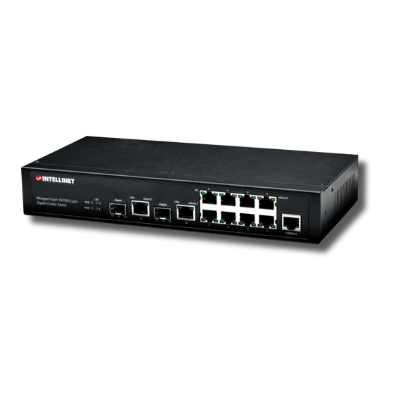
Thank you for purchasing the INTellINeT NeTWoRK SolUTIoNS Fast ethernet Managed ™ Switch, Model 523769. Equipped with eight 10/100Base-TX ports plus two combo 1000 Mb slots (fiber options are SFP-type and 1000Base-SX/LX/LHX), this device is designed with SNMP, RMON, flexible network management and monitoring options for increased efficiency and performance. -
Page 4: Table Of Contents
tablE of contEnts section page Introduction ...................... 3 Hardware ....................6 Front Panel ......................6 Rear Panel ......................6 Connectors ......................6 1.3.1 10/100Base-TX Ports ..................6 1.3.2 10/100/1000Base-T Ports ................. 6 1.3.3 SFP Slots for SFP Modules ................7 InstallatIon .................... - Page 5 4.3.1.3 DHCP Configuration ..................26 4.3.2 Configuration ....................26 4.3.2.1 Port Configuration ..................26 4.3.2.2 Port Status ...................... 27 4.3.3 Bridge Menu ....................27 4.3.3.1 Bridge Configuration (Enable/Disable STP, Jet Ring or Xpress Ring) ..28 4.3.3.2 STP System Configuration ................28 4.3.3.3 STP Per-Port Configuration ................
-
Page 6: Hardware
1 hardwarE The Fast ethernet Managed Switch was developed with a host of features — including both Xpress Ring and Jet Ring — that makes it particularly well-suited for SoHo applications that demand the utmost in reliability. The Jet Ring offers a recovery time of less than 300 ms in case of any network-link failure;... -
Page 7: Sfp Slots For Sfp Modules
copper ports support network speeds of 10/100/1000 Mbps. These two ports are located next to their corresponding SFP-type fiber slots, and each of these RJ-45 ports is interchangeable with its corresponding SFP slot. The Gigabit copper port will have the same number as its corresponding SFP slot. Once an SFP fiber slot is connected, the correspondingly numbered RJ-45 port won’t function. -
Page 8: Sfp Modules And Fiber Cable
connection is provided via a terminal block located at the top of the switch. The switch’s power supply automatically self-adjusts to the local power source and may be powered on without having any or all lAN segment cables connected. Check the front-panel as the device is turned on to verify that the PWR led lights. -
Page 9: Led Indicators
2.2.7 lEd indicators This switch is equipped with unit leds (indicating the status of the switch) and port leds (positioned alongside each copper port and indicating the status of the connections). All leds light green. condition status Switch is being fed primary power. Primary power is off or a failure has occurred. -
Page 10: Xpress Ring
3.2 Xpress ring Xpress Ring enables networks to recover from link failure within 50 ms. Unlike Jet Ring, however, it needs some network configuration efforts. The user must assign two ring ports for each switch in the ring. The user must also assign the “arbiter” switch, which will decide if it is necessary to activate the backup path. -
Page 11: Connecting A Hyperterminal
4.1.1 connecting via hyperterminal 1. Verify the console cable (RJ-45 to DB9) connection between the switch and workstation. 2. launch the terminal emulation program on the remote workstation and turn on the switch. Be sure to select the correct CoM port. Click “oK.” 3. -
Page 12: Menu-Driven User Interface Via Telnet
With HyperTerminal, command lines are the same as those for Telnet. You can continue to use HyperTerminal with the instructions provided. otherwise, log out by entering “exit” and pressing the “enter” key. The switch can then be configured via an HTTP Web browser or Telnet with menu-driven or command line interfaces. -
Page 13: Dhcp Configuration Menu
4.2.2 DHCP Configuration Menu This screen presents the option of either disabling or enabling dHCP Client. When enabled, dHCP Leased Time and DHCP Expiry Time are displayed in seconds, as shown. 4.2.3 device control Menu Port Configuration: Configure various parameters for each of the switch’s ports. -
Page 14: Bridge Menu
Port No.: In the settings panel at the bottom of the screen, use the “enter” and “Tab” keys to position the cursor in the desired field and enter whichever port number you want to configure. Name: The name assigned to a port for keeping records of the connections. Type: The type of a port connector (fiber or RJ-45). - Page 15 Priority: When setting the bridge priority, the limit can be from 0 (the highest priority) to 65535 (the lowest priority). The bridge priority is used in selecting the root device, root port and designated port. The device with the highest priority becomes the STA root device. However, if all devices have the same priority, the device with the lowest MAC address will then become the root device.
-
Page 16: Vlan Menu
4.2.3.2.4 J TaTus If Jet Ring is enabled, you can view the Jet Ring status. The switch will automatically detect which port is attached to other switches (or other Jet Ring-enabling switches) to establish the Jet Ring. You can see how many nodes are connected in the ring and which node is working as master, arbiter or member. - Page 17 4.2.3.3.1 P Vlan C asED onfiguRaTions Port ID Members: Set the VlAN association of one port to another. Blank spaces indicate there is no set VlAN association. default is that all ports are associated, though you can also set all ports as isolated. Ports 1 –...
- Page 18 frame is simply kept unchanged when it is sent out from a “tagging” egress port, generally to a 802.1Q switch or a standard VLAN-aware device. 4.2.3.3.3 T asED nfoRmaTion ngREss EhaVioR PVID: The port VlAN Id is assigned to all untagged frames received on the designated port. The limit is between 1 and 4095.
-
Page 19: Rate Control Configuration
4.2.3.3.5 m Vlan anagEmEnT This is the VlAN Id to which the in-band management stations belong. The PVId of the port that receives the management messages must be the same as the Management VlAN Id. Web and Telnet sessions will be disconnected after the Management VlAN is changed. -
Page 20: Trunk Configuration
4.2.3.6 Trunk Configuration Port Trunking defines a network link aggregation and trunking method that specifies how to create a single high-speed logical link that combines several low-speed physical links. The switch supports a maximum of four trunk groups for 100 Mbps ports, and an additional trunk group for Gigabit ports. - Page 21 4.2.3.8.1 maC T ablE Settings with a “T” in the right-hand column indicate that the MAC (media access control) Is learned from a trunk port; settings with a “P” indicate that the MAC is learned from a downlink port. 4.2.3.8.2 l maC a DDREss EaRning...
-
Page 22: Quality Of Service (Qos)
4.2.3.8.4 maC l imiT onfiguRaTion 4.2.3.9 Quality of service (Qos) This sub-menu presents three further options: Base Configuration, Tag Priority Table and IP ToS (type of service) Priority Table. 4.2.3.9.1 b onfiguRaTion This screen presents a Schedule Mode choice between “weighted fair queuing”... -
Page 23: Management Setup Menu
4.2.3.9.3 T RioRiTy ablE 4.2.4 Management setup Menu After logging in to the system, use this menu to configure settings for remote access via the SNMP agent, to configure the email alarm or to upgrade the firmware. NOTE: You should set the community string that controls access to the onboard SNMP agent via in-band management software (SNMP Configuration). -
Page 24: Email Alarm Configuration
same community string. In actuality, this management method uses two community strings: the GeT community string and the SeT community string. If the SNMP network management station only knows the SeT community string, it can both read and write to the management information bases (MIBs). -
Page 25: User Configuration Menu
4.2.4.4 User Configuration Menu 4.2.5 Port counter Menu This screen displays all of the ports’ statistics. 4.2.6 system restart Menu You can remotely restart the switch or reset factory defaults via software without turning it off. WARNING: If you highlight either “Restore Factory default Settings” or “System Reset” and press the “enter”... -
Page 26: System Information
Fast ethernet Managed Switch INTellINeT NeTWoRK SolUTIoNS 523769 4.3.1.1 system Information Description/Model Name: Identifies the device. Object ID: This is the Id or serial number of the switch. Up Time: This is the total time the system has been operating. -
Page 27: Port Status
Duplex Status: displays the status (either “Half” or “Full”). Duplex Setting: Select either “Half” or “Full.” Link: displays the status. Auto: Select “enable” or “disable” for auto-negotiation of the copper ports. Flow Control: Select “enable” or “disable” for each port. Click “Undo”... -
Page 28: Bridge Configuration (Enable/Disable Stp, Jet Ring Or Xpress Ring)
The Spanning Tree Algorithm is used for detecting and disabling network loops, and to provide backup links between switches, bridges or routers. This allows the switch to communicate and interact with other bridging (STA-compliant) devices in a network to ensure that only one route exists between any two stations. -
Page 29: Stp Per-Port Configuration
4.3.3.3 STP Per-Port Configuration STP allows the switch to assign a priority status to each of its ports with respect to other networking nodes in the network. In other words, STP determines the best route for data to flow given the priority level of each node on the network. -
Page 30: Vlan Menu
Select Ring Port – 1: Enter the first ring port with the link composing part of the Xpress Ring. Select Ring Port – 2: enter the second ring port with the link composing part of the Xpress Ring. Port Status: displays the ring port status either as “Forwarding” (packet transmitting and receiving) or as “Blocking”... -
Page 31: Tag-Based Info
4.3.4.1.2 T Vlan P asED onfiguRaTion This screen is enabled when the VlAN Type (see 4.3.4.1 above) is set as “Tagging Base,” and lets you configure the way each port treats incoming frames marked for tag-based VLANs. PVID: Set the port’s VlAN Id, which is assigned to all untagged frames received on this port. The limits are 1 –... -
Page 32: Management Vlan
in or transmitted from the port. The tagged VlAN information in the frames can later be used by other 802.1Q-compliant devices for forwarding decisions. No: The port is not participating in the VLAN as identified by the selected VID (VLAN ID). Click “Modify”... -
Page 33: Port Mirroring
This screen is for setting the jumbo packet length and rate control for each port on the switch. Jumbo Packet Length: Select the size of packets: 1535 for double-tagged packets or jumbo packets; 1522 for normally tagged packets. 1518 bytes is actually allowed for untagged packets. Ingress Limit Mode: Select one of four multicast rate limit options to block the specified traffic from the port. -
Page 34: Igmp Menu
4.3.8 igMP Menu The IGMP (Internet Group Management Protocol) menu is used to configure IGMP snooping. IGMP is a protocol through which hosts can register with their local router for multicast services. If there is more than one multicast router on a given sub-network, one of the routers assumes the responsibility of keeping track of group membership. -
Page 35: Lock Mac Address Learning
4.3.9.2 lock Mac address learning You can stop specific ports from learning MAC addresses by selecting and “locking” them here. Click “Save” to retain newly entered information; click “Undo” to restore previously saved configurations. 4.3.9.3 Static MAC Configuration on this screen, you can select a static MAC configuration for certain port(s) of the switch. -
Page 36: Qos Menu
learning process will be conducted every three minutes, so if you change the network interface card of the PC or IP appliance the new MAC address will be learned in three minutes by the switch, with the set quantity limitations. Action: The MAC limit function can be disabled or enabled per port. -
Page 37: Ip Tos Priority
4.3.10.3 Ip tos priority This screen presents up to 63 different priorities. Select the most suitable combination. 4.3.11 Management Configuration This sub-menu features the serial port configuration screen, which can be utilized while accessing the switch via the console port. Management Mode, Baud Rate, Data Bits, Stop Bits, Parity: These are the default CoM port properties. -
Page 38: Email Alarm Configuration
managers may be assigned. IP Address: enter the IP address of terminals for when abnormalities on a connection occur and an alarm needs to be sent. The alarm will be sent to these terminals: Enter their community names and disable or enable their alarm function accordingly. Community Name: Enter the community names. -
Page 39: Firmware Download (Upgrade System)
all parameters and statistics. It’s recommended that you define a new administrator password, record it and put it in a safe place. NOTE: Passwords can consist of up to 12 alphanumeric characters (up to 20 for the username), and they are not case sensitive. Five users can be configured by the switch. -
Page 40: Cli Via The Console Port (Basic Instructions)
4.4 cli via the console Port (basic instructions) This section continues the initial setup in section 4.1 by presenting some basic instructions for using command line interface to configure the switch. 1. Open a command-prompt window and enter the following command line, in which the “xxx” segments represent the IP address: telnet xxx.xxx.xxx.xxx. -
Page 41: System Configurations
4.4.3 System Configurations enter the command line and follow the argument list. NOTE: Be sure to include a space between command segments; for example: set eth0 ip xxx.xxx.xxx.xxx. A confirmation message will follow. By using a similar command line, all the other available system parameters — as listed below —... -
Page 42: Switch Configurations
4.4.3.1 Switch Configurations enter the command line and follow the argument list. NOTE: Be sure to include a space between command segments; for example, for setting the switch age: set switch age 1. A confirmation message will follow. NOTE: Each switch age unit is equal to 16 seconds. The default is 304 seconds. -
Page 43: Virtual Lan (Vlan) Configurations
4.4.3.4 Virtual LAN (VLAN) Configurations enter the command line and follow the argument list. NOTE: Be sure to include a space between command segments; for example, for changing or setting the VLANs: set vlan. A confirmation message will follow. By using a similar command line, the other port parameters can be modified to suit your own requirements. -
Page 44: Set Email
To set up the email list and other parameters, use the following example. Enter the command line and press the “Enter” key: set email to 1 admin@MyCompany.com set email from 523769@MyCompany.com (See 4.3.13 to enable the email alarm.) 5 troublEshooting The network administrator can observe and monitor most areas of the switch status using the led indicators on the front panel to quickly identify problems. -
Page 45: Specifications
6 sPEcifications appendix a rJ-45 cables When connecting your network devices, use a standard Cat3 eight-way cable for a 10Base-T configuration and a Cat5 cable for 100Base-TX. The pin assignments are as follows: Pair White/Orange Pair Orange/White Pair White/Green Pair Blue/White Pair White/Blue... - Page 46 standards • Bandwidth control options: 128 kbps, 256 kbps, 512 kbps, 1 Mbps, 2 Mbps, 4 Mbps, 8 Mbps, • Ieee 802.3 (10Base-T ethernet) 16 Mbps, 32 Mbps, 64 Mbps, no limit • Ieee 802.3u (100Base-TX Fast ethernet) • Port Mirroring •...
- Page 48 Are you completely satisfied with this product? Please contact your INTellINeT NeTWoRK SolUTIoNS dealer ™ with comments or questions. Copyright © INTellINeT NeTWoRK SolUTIoNS All products mentioned are trademarks or registered trademarks of their respective owners.
Need help?
Do you have a question about the 523769 and is the answer not in the manual?
Questions and answers