
Subscribe to Our Youtube Channel
Related Manuals for JUMO dTRANS T07


Summary of Contents for JUMO dTRANS T07
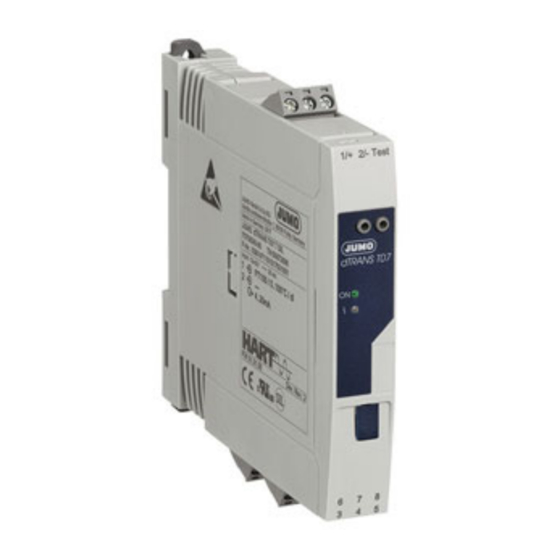
- Page 1 JUMO dTRANS T07 Two-channel temperature transmitter with HART®/Ex/SIL for installation in terminal head, B form, and for mounting on DIN rails Brief Instructions 70708000T97Z001K000 V2.00/EN/00681622...
-
Page 3: Table Of Contents
Contents Contents Important information about this document......5 How this document works and how to use it........5 1.1.1 How this document works . - Page 4 Contents Electrical connection ......... . . 18 Installation notes .
-
Page 5: Important Information About This Document
Important information about this document 1 Important information about this document How this document works and how to use it 1.1.1 How this document works These instructions contain information that is required in the various phases of the device's lifecycle: from product identification, product acceptance and storage to mounting, connection, basic operation, and startup, through to troubleshooting, maintenance and disposal. -
Page 6: Other Applicable Device Documentation
Safety information and technical data for electrical equipment for JUMO dTRANS T07 potentially explosive areas according to Directive 2014/34/EU (ATEX). NOTE! The documents listed are available: At www.jumo.net, under "Documentation" on the product page for the dTRANS T07. Registered trademarks HART® Trademark registered to the FieldComm Group™... -
Page 7: Basic Safety Information
Follow the instructions in this manual Intended use The dTRANS T07 series is a range of universal and configurable transmitters with either one or two sen- sor inputs for RTD temperature probes (RTD), thermocouples (TC), potentiometers, and voltage sen- sors. -
Page 8: Identifying The Device Version
Compare the specifications on the nameplate with your order documents. The supplied device version can be identified using the order code in 10. Example: Type 707086/8-06 (dTRANS T07 B Ex SIL – Two-wire transmitter with Ex and SIL approval for installation in terminal head, form B) (2) Part no. - Page 9 Compare the specifications on the nameplate with your order documents. The supplied device version can be identified using the order code in 10. Example: Type 707088/8-06 (dTRANS T07 T Ex SIL – 2-wire transmitter with Ex and SIL approval for mounting on DIN rails) (2) Part no.
-
Page 10: Order Details
T07 B Ex – Two-wire transmitter with Ex approval for in- stallation in terminal head, form B 707086 dTRANS T07 B Ex SIL – Two-wire transmitter with Ex and SIL ap- proval for installation in terminal head, form B 707087 dTRANS T07 T Ex –... -
Page 11: Accessories
BD7 plug-in display for dTRANS T07 BD7 00672701 AB7 terminal head for dTRANS T07 B 00672702 FG7 field housing with display window for dTRANS T07 B 00672705 MW7 wall mounting set for field housing 00672707 MR7 tube mounting set for field housing... -
Page 12: Mounting
Conditions for installation 4.2.1 Dimensions Head transmitter Ø 5 Spring deflection mounting screws ≥ 5 mm (not with US-M4 mounting screws) Mounting elements for plug-on display BD7 internal service interface (not intended for use) DIN rail device dTRANS T07 17.5 114.9... -
Page 13: Mounting Site
DIN rail device protection type: IP20 NOTE! For application in potentially explosive areas, the limit values for the certificates and approvals (see Ex safety manual of dTRANS T07) must be met. Mounting A cross-head screwdriver is required when mounting the head transmitter. -
Page 14: Mounting The Head Transmitter
4 Mounting 4.3.1 Mounting the head transmitter Mounting a terminal head, form B, according to DIN 43729 ( ) 7 ( ) 6 ( ) 5 ( ) 4 ( ) 3 ( ) 2 ( ) 8 ( ) 9 ( ) 1 (1) Terminal head (6) Mounting springs... - Page 15 4 Mounting Mounting in field housing for wall mounting (A) or pipe mounting (B) ( ) 1 (1) Lid to field housing (3) Head transmitter (2) Mounting screws with springs (4) Field housing Process: 1. Open the lid (1) to the field housing (4). 2.
- Page 16 4 Mounting Mounting on DIN rails according to IEC 60715 ( ) 1 (1) Mounting screws with springs (4) Mounting element for DIN rail (2) Head transmitter (5) DIN rail (3) Retaining rings Process: 1. Press the mounting element (4) onto the DIN rail (5) until it engages. 2.
-
Page 17: Din Rail Device Installation
4 Mounting 4.3.2 DIN rail device installation NOTE! Mount the device vertically and make sure it is pointing in the right direction (sensor connection at the bottom/voltage supply at the top)! If the installation position is wrong, the measurement will not meet the maximum measuring accuracy when connecting a thermocouple and when using the internal cold junction. -
Page 18: Electrical Connection
Electrical connection 5 Electrical connection Installation notes A cross-head screwdriver is required when wiring the head transmitter with screw terminals. Use a cross- head screwdriver to wire DIN rail devices. CAUTION! Destruction of electronic components or the entire electronics system ... -
Page 19: Terminal Assignment For The Head Transmitter
5 Electrical connection Terminal assignment for the head transmitter Connection for Explanations Terminals Voltage supply max. = (U max. – 11 V) ÷ 0.023 A DC 11 to 42 V (standard) = load resistance DC 11 to 32 V (SIL) = voltage supply Current output –... - Page 20 5 Electrical connection Connection for Explanations Terminals Analog input (sensor input) 2 RTD temperature probe ▪ Sensor current ≤ 0.3 mA ▪ Compensation for the line resistance is possible 2-wire circuit (0 to 30 Ω) RTD temperature probe ▪ Sensor current ≤ 0.3 mA ▪...
-
Page 21: Terminal Assignment For Din Rail Devices
5 Electrical connection Terminal assignment for DIN rail devices Connection for Explanations Terminals Voltage supply max. = (U max. – 12 V) ÷ 0.023 A DC 12 to 42 V (standard) = load resistance DC 12 to 32 V (SIL) = voltage supply Current output 4 to 20 mA... - Page 22 5 Electrical connection Connection for Explanations Terminals Resistance/potentiometer ▪ Sensor current ≤ 0.3 mA ▪ Sensor line resistance max. 50 Ω per line 4-wire circuit Thermocouple Voltage sensor Analog input (sensor input) 2 RTD temperature probe ▪ Sensor current ≤ 0.3 mA ▪...
-
Page 23: Connecting Sensor Lines
(TC), voltage sen- 2-wire 3-wire 4-wire RTD or potentiometer, 2- wire RTD or potentiometer, 3- wire RTD or potentiometer, 4- wire Thermocouple (TC), voltage sensor Admissible combination in SIL mode; refer to the "SIL safety manual" for dTRANS T07. -
Page 24: Connecting The Voltage Supply And Signal Cable
5 Electrical connection Connecting the voltage supply and signal cable CAUTION! Destruction of electronic components Do not install or wire the transmitter under operating voltage. NOTE! Cable specification: ● A normal installation cable will suffice if you are only using the analog signal. ●... -
Page 25: Shielding And Earthing
5 Electrical connection Shielding and earthing Optimum electromagnetic compatibility (EMC) is only guaranteed if system components and, above all, wires are shielded and if the shield form a shell that is as complete as possible. HART® communication allows for three different types of shield: •... - Page 26 5 Electrical connection Electrical connection Important information Does the voltage supply match the specifications on the Head transmitter: U = 11 to 42 V nameplate? DIN rail device: U = 12 to 42 V SIL mode: U = 11 to 32 V for head transmitters or U = 12 to 32 V for DIN rail devices...
-
Page 27: Operation
6 Operation Measured value display and operating elements 6.1.1 Head transmitter with optional BD7 plug-in display NOTE! The plug-in display can also be reordered, see "Accessories" chapter in the dTRANS T07 operating manual. 6.1.2 Display elements Head transmitter ( ) 1 Pos. -
Page 28: Operating On-Site
6 Operation Status signals Symbols Meaning "Operating fault" error message An operating fault has occurred. The measured value is no longer valid. An error message and "- - - -" (no valid mea- sured value available) alternate in the display. Detailed information about the error messages can be found in the device's operating manual. -
Page 29: Transmitter Configuration And Hart® Protocol
The transmitter is configured and the measured value requested using the HART® protocol. The follow- ing operating tools can be used for this: • PACTWare™ (DTM-based systems asset management tool) • Field communicator 375/475 (Emerson Process Management) NOTE! The configuration of the device-specific parameters is described in detail in the dTRANS T07 operating manual. -
Page 30: Startup
• Deactivate software write protection using the operating tool, see description of the device parame- ter, "Defining the write protection code" in the dTRANS T07 operating manual. NOTE! When the hardware write protection is active (write protection switch on the back of the plug-in display is in the "ON"... - Page 32 JUMO GmbH & Co. KG JUMO Instrument Co. Ltd. JUMO Process Control, Inc. Street address: JUMO House 6733 Myers Road Moritz-Juchheim-Straße 1 Temple Bank, Riverway East Syracuse, NY 13057, USA 36039 Fulda, Germany Harlow, Essex, CM20 2DY, UK Delivery address:...
Need help?
Do you have a question about the dTRANS T07 and is the answer not in the manual?
Questions and answers