Lectrosonics UCR401 Instruction Manual
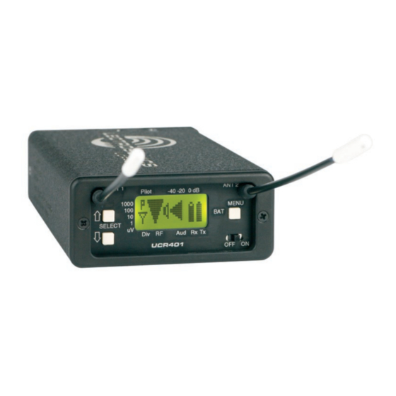
Compact wireless receiver
Hide thumbs
Also See for UCR401:
- Quick start manual (12 pages) ,
- Instruction manual (48 pages) ,
- Instruction manual (28 pages)
Table of Contents
Advertisement
Quick Links
Download this manual
See also:
Instruction Manual
Advertisement
Table of Contents

Subscribe to Our Youtube Channel
Related Manuals for Lectrosonics UCR401


Summary of Contents for Lectrosonics UCR401
-
Page 1: Digital Hybrid Wireless
INSTRUCTION MANUAL UCR401 Compact Wireless Receiver Featuring Digital Hybrid Wireless Technology ® U.S. Patent 7,225,135 Fill in for your records: Serial Number: Purchase Date: Rio Rancho, NM, USA www.lectrosonics.com... - Page 2 UCR401 LECTROSONICS, INC.
- Page 3 UHF Digital Hybrid Wireless Receiver ® Digital Hybrid Wireless The Lectrosonics Digital Hybrid Wireless uses in- novative technology to combine the new advantages of digital audio with the advantages of analog RF trans- mission, thus delivering the superior sound quality of a digital system and the excellent range of an analog sys- tem.
- Page 4 UCR401 LECTROSONICS, INC.
-
Page 5: Table Of Contents
Antenna Use and Placement ................................16 Setup and Operating Instructions ...............................17 Installing/Replacing Batteries................................17 Adjusting Audio Output ..................................17 Finding Clear Frequencies ..................................18 Locking and Unlocking the UCR401 ..............................19 Pre-coordinated Frequencies ................................20 Compatible Frequency Table ................................20 Compatibility Diagram ..................................21 Diagnostics ......................................22 Multi-channel System Checkout................................22 Pilot Tone Bypass ....................................22... - Page 6 UCR401 LECTROSONICS, INC.
-
Page 7: General Technical Description
The UCR401 is a portable, high performance, triple- conversion, frequency synthesized, UHF receiver fully The UCR401 is frequency agile and can be set to compatible with all Lectrosonics 400 Series transmit- operate on any one of 256 frequencies within its tuning ters, Lectrosonics wideband UHF analog systems. -
Page 8: If Amplifiers And Saw Filters
In the FM signal, rather than a conventional quadrature order to reduce this noise the UCR401 is equipped with detector. This unusual design eliminates thermal drift, a Smart Noise Reduction algorithm, which removes improves AM rejection, and provides very low audio hiss without sacrificing high frequency response. -
Page 9: Supersonic Noise-Based Dynamic Filter And Squelch
To assist in matching the audio levels of equipment con- NORMAL - tune in single channel increments nected to the UCR401, a 1 kHz audio test tone, adjust- GRP x - tune in precoordinated intermod-free able from -50 to +5 dBu in 1 dB increments, is available frequencies (x is A, B, C, D, U or V)) at the XLR connector. -
Page 10: Front Panel Controls And Functions
The SELECT Up/Down buttons are used to select vari- Display that is used to monitor system operation and ous options within each display selection and for setting configure the UCR401. the operating frequency of the receiver. MENU Button Power ON/OFF Switch... -
Page 11: Main Window (Lcd)
UHF Digital Hybrid Wireless Receiver ® Main Window (LCD) Audio Levels - reference levels SEL Up Button - control up for audio signal modulation from one step transmitter MENU Button - changes windows SEL Down Button - control down one step Power ON/OFF switch RF levels - reference for RF level screen icon The Main Window displays information concerning the... -
Page 12: Menu Selections From Main Window
UCR401 Menu Selections from Main Window Main Window Frequency Press All Buttons Scan Mode Pilot Off/On Hold MENU & press UP SELECT Press & Hold MENU Lock/Unlock Setup Window Press UP Frequency Level Press Window MENU Press MENU Press (Press UP / DOWN to adjust) -
Page 13: Setup Window
(factory default setting), a moder- monitoring. Four different types of ate amount of noise reduction is batteries are commonly used in Lectrosonics transmit- applied, dramatically reducing ters: 9 Volt alkaline, 9 Volt lithium, AA alkaline, and AA hiss with virtually no discernible lithium. -
Page 14: Tuning
User Programmable Frequency Group Behavior 100 - Lectrosonics 100 Series compatibility mode. The user programmable frequency groups “U” or “V” 200 - Lectrosonics 200 Series compatibility mode. work very similarly to the factory groups with a few exceptions. -
Page 15: Frequency Scan Mode
In the FINE VIEW window, each vertical band repre- Once you leave the scan mode, the Frequency Window sents one frequency the UCR401 is capable of tuning. will be displayed. Set your transmitter switches to the The upper right corner shows the transmitter switch same settings as shown on the display and your system settings for the frequency indicated by the cursor. -
Page 16: Antenna Use And Placement
Long cable runs can cause location. If dropouts are still a problem, try moving the substantial signal loss. Lectrosonics has in-line RF antennas to an entirely different location in the room or amplifiers suitable for compensating for long cable moving them closer to the transmitter location. -
Page 17: Setup And Operating Instructions
Normal levels should cause the UCR401’s audio level icon to fluctuate fully. This will result in the best possible signal to noise ratio for the system. -
Page 18: Finding Clear Frequencies
If the output is too low, you may hear steady noise (hiss) along with the audio. The UCR401 6. If necessary, press the MENU button to zoom in for audio output is designed to drive any audio input greater detail. -
Page 19: Locking And Unlocking The Ucr401
LOCKED, all settings can be altered. Frequency Select Screen The UCR401 can only be LOCKED or UNLOCKED from any of the main windows. (There are four of them.) Also, it cannot be switched between LOCKED and UN- LOCKED modes when it is in a scanning mode or from other subordinate screens. -
Page 20: Pre-Coordinated Frequencies
The frequencies can be used Grp a, the eight just FREQ SW SET US TV CH with Digital Hybrid and analog Lectrosonics wireless 570.100 tv30 below them comprise equipment. Compatibility with other brands is likely, but 570.700 tv30 Grp b, and so on. -
Page 21: Compatibility Diagram
UHF Digital Hybrid Wireless Receiver ® Compatibility Diagram BLOCK 24 BLOCK 25 Compatibility follows the pattern illustrated in the dia- FREQ SW SET US TV CH FREQ SW SET US TV CH 621.300 tv39 646.900 tv43 gram at right. 621.900 tv39 647.500 tv43... -
Page 22: Diagnostics
UCR401 Diagnostics Multi-channel System Checkout 4. Turn each transmitter off one at a time. Interference can result from a wide variety of sources including TV station signals, other wireless equipment With all transmitters and receivers turned on, turn each transmitter off one at a time, in turn, and look in use nearby, or from intermodulation within a multi- channel wireless system itself. -
Page 23: Replacement Parts And Accessories
UHF Digital Hybrid Wireless Receiver ® Replacement Parts and Accessories CCMINI CCMINI Zippered, padded vinyl system pouch DCR12/A4U Power Supply; 90-240 VAC, 50/60 Hz input; 12 VDC (regulated), 400 mA max. output. VSR1 Thin velcro loop for power cable strain relief. PS70 A/C power supply with 3-pin NEMA socket on hous- ing, 100-240 VAC input;... -
Page 24: Troubleshooting
UCR401 Troubleshooting Symptom Possible Cause INITIAL POWER ON LCD display not active or lit External power supply disconnected or inadequate. Wrong polarity power source. The external power input jack requires POSITIVE (+) to be on the center pin. Battery gets warm and doesn’t work. - Page 25 If the noise is still present, then the problem is not in the transmitter. If noise is still present when the transmitter is turned off, try lowering the audio output level on the UCR401 and see if the noise lowers correspondingly. If the noise remains, the problem is not in the receiver.
-
Page 26: Specifications And Features
UCR401 Specifications and Features Signal to Noise Ratio (dB): Operating Frequencies (MHz): SmartNR No Limiting w/Limiting (overall system, 400 Series mode) 103.5 108.0 Block 21: 537.600 - 563.100 Block 22: 563.200 - 588.700 NORMAL 107.0 111.5 Note: The dual envelope “soft”... -
Page 27: Service And Repair
There are no adjustments inside that will make a malfunctioning unit start working. LECTROSONICS’ Service Department is equipped and staffed to quickly repair your equipment. In warranty repairs are made at no charge in accordance with the terms of the warranty. Out-of-warranty repairs are charged at a modest flat rate plus parts and shipping. -
Page 28: Limited One Year Warranty
This warranty does not apply to used or demonstrator equipment. Should any defect develop, Lectrosonics, Inc. will, at our option, repair or replace any defective parts without charge for either parts or labor. If Lectrosonics, Inc. cannot correct the defect in your equipment, it will be replaced at no charge with a similar new item.
Need help?
Do you have a question about the UCR401 and is the answer not in the manual?
Questions and answers