
Subscribe to Our Youtube Channel
Related Manuals for Lectrosonics UCR401A


Summary of Contents for Lectrosonics UCR401A
- Page 1 INSTRUCTION MANUAL UCR401 Compact Wireless Receiver Featuring Digital Hybrid Wireless Technology ® U.S. Patent 7,225,135 Fill in for your records: Serial Number: Purchase Date: Rio Rancho, NM, USA www.lectrosonics.com...
- Page 2 UCR401 LECTROSONICS, INC.
- Page 3 UHF Digital Hybrid Wireless Receiver ® Digital Hybrid Wireless The Lectrosonics Digital Hybrid Wireless uses in- novative technology to combine the new advantages of digital audio with the advantages of analog RF trans- mission, thus delivering the superior sound quality of a digital system and the excellent range of an analog sys- tem.
- Page 4 UCR401 LECTROSONICS, INC.
-
Page 5: Table Of Contents
UHF Digital Hybrid Wireless Receiver ® Table of Contents General Technical Description ................................7 Diversity Reception ....................................7 MIicrocontroller, PLL and VCO Circuits..............................7 IF Amplifiers and SAW Filters ................................8 Digital Pulse Counting Detector ................................8 DSP-Based Pilot Tone ...................................8 .......................................8 Smart Squelch ™ Smart Noise Reduction (SmartNR ) ..............................8 ™... - Page 6 UCR401 LECTROSONICS, INC.
-
Page 7: General Technical Description
UHF receiver fully The UCR401 is frequency agile and can be set to compatible with all Lectrosonics 400 Series transmit- operate on any one of 256 frequencies within its tuning ters, Lectrosonics wideband UHF analog systems. DSP range. -
Page 8: If Amplifiers And Saw Filters
Because it isn’t simply a sophisticated variable low pass filter as in Lectrosonics’s 195 and 200 series analog de- muting (squelch). Brief delays are applied to eliminate thumps, pops or other transients that can occur when signs, much greater transparency is obtained. -
Page 9: Supersonic Noise-Based Dynamic Filter And Squelch
MODE 3 - compatible with certain Audio Output Level non-Lectrosonics transmitters) IFB - compatible with all Lectrosonics IFB A setup screen is provided for adjusting the audio out- transmitters. put level in 1 dB increments from -50 to +5 dBu using MODE 6 - compatible with certain the front panel SEL Up and Down buttons. -
Page 10: Front Panel Controls And Functions
The jack and plug feature twist-lock retention. The Power Input Jack will also accommodate non-locking plugs. LECTROSONICS, INC. -
Page 11: Main Window (Lcd)
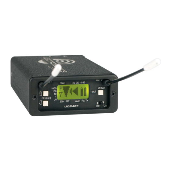
UHF Digital Hybrid Wireless Receiver ® Main Window (LCD) Audio Levels - reference levels SEL Up Button - control up for audio signal modulation from one step transmitter MENU Button - changes windows SEL Down Button - control down one step Power ON/OFF switch RF levels - reference for RF level screen icon The Main Window displays information concerning the... -
Page 12: Menu Selections From Main Window
The in the upper right hand corner of the Frequency RX voltage changes to EX when operating on external window. power and displays the external power source voltage. (Disclaimer: We cannot guarantee 0.1 Volt accuracy.) LECTROSONICS, INC. -
Page 13: Setup Window
(factory default setting), a moder- monitoring. Four different types of ate amount of noise reduction is batteries are commonly used in Lectrosonics transmit- applied, dramatically reducing ters: 9 Volt alkaline, 9 Volt lithium, AA alkaline, and AA hiss with virtually no discernible lithium. -
Page 14: Tuning
User Programmable Frequency Group Behavior 100 - Lectrosonics 100 Series compatibility mode. The user programmable frequency groups “U” or “V” 200 - Lectrosonics 200 Series compatibility mode. work very similarly to the factory groups with a few exceptions. -
Page 15: Frequency Scan Mode
UHF Digital Hybrid Wireless Receiver ® Frequency Scan Mode Scan & View Window Elements Fine View Window Elements Cursor - shows relative position Switch Settings - shows the of the scanner within the transmitter switch settings Transmitter 25 MHz band of the receiver. - will change rapidly while the Cursor (center bar) Switch Settings... -
Page 16: Antenna Use And Placement
Long cable runs can cause location. If dropouts are still a problem, try moving the substantial signal loss. Lectrosonics has in-line RF antennas to an entirely different location in the room or amplifiers suitable for compensating for long cable moving them closer to the transmitter location. -
Page 17: Setup And Operating Instructions
UHF Digital Hybrid Wireless Receiver ® Setup and Operating Instructions Installing/Replacing Batteries Adjusting Audio Output 1. As per the instructions engraved on the Battery 1. Install fresh batteries or connect an external power Door, use your thumb to lift and open door. Then source to the UCR401. -
Page 18: Finding Clear Frequencies
Look for clear channels in the spectrum where scanning. SEL Up Button SEL Down Button MENU Button Press all three buttons at the same time and the receiver will start scanning. LECTROSONICS, INC. -
Page 19: Locking And Unlocking The Ucr401
UHF Digital Hybrid Wireless Receiver ® To UNLOCK the UCR401 Press all three buttons at Press and hold the MENU button until a bar tracks hori- the same time to move to zontally across the screen and the word “UNLOCKED” Frequency Select Screen is displayed on the LCD screen. -
Page 20: Pre-Coordinated Frequencies
The frequencies can be used Grp a, the eight just FREQ SW SET US TV CH with Digital Hybrid and analog Lectrosonics wireless 570.100 tv30 below them comprise equipment. Compatibility with other brands is likely, but 570.700 tv30 Grp b, and so on. -
Page 21: Compatibility Diagram
UHF Digital Hybrid Wireless Receiver ® Compatibility Diagram BLOCK 24 BLOCK 25 Compatibility follows the pattern illustrated in the dia- FREQ SW SET US TV CH FREQ SW SET US TV CH 621.300 tv39 646.900 tv43 gram at right. 621.900 tv39 647.500 tv43... -
Page 22: Diagnostics
Only the matching receiver should indi- cate a signal. Change frequencies on either system slightly until all channels pass this test, then check again to see that all channels are still clear as done in step 2. LECTROSONICS, INC. -
Page 23: Replacement Parts And Accessories
UHF Digital Hybrid Wireless Receiver ® Replacement Parts and Accessories CCMINI CCMINI Zippered, padded vinyl system pouch DCR12/A4U Power Supply; 90-240 VAC, 50/60 Hz input; 12 VDC (regulated), 400 mA max. output. VSR1 Thin velcro loop for power cable strain relief. PS70 A/C power supply with 3-pin NEMA socket on hous- ing, 100-240 VAC input;... -
Page 24: Troubleshooting
In the other compatibility modes, no pilot tone is used and the “P” is never displayed. Audio is present whenever the receiver detects a sufficiently strong signal. Regardless of the compatibility mode, activating the “pilot bypass” function causes a lowercase “b” to appear in the pilot indicator position on the main window and forcibly unsquelches the audio. LECTROSONICS, INC. - Page 25 UHF Digital Hybrid Wireless Receiver ® Symptom Possible Cause ANTENNAS AND RF SIGNAL STRENGTH RF Level is weak Receiver may need to be moved or reoriented. Antenna on transmitter or receiver may be defective or poorly connected - double check antennas. Improper length of antenna, or wrong antenna on transmitter or receiver.
-
Page 26: Specifications And Features
1 kHz, -50 dBu to +5 dBu output, 1% THD Transmitter battery type selection: 9V alkaline, 9V lithium, AA alkaline, AA lithium, NiMH Phase invert: Audio output phase normal or inverted SmartNR (noise reduction): OFF, NORMAL, FULL modes (available in 400 Series mode only) LECTROSONICS, INC. -
Page 27: Service And Repair
There are no adjustments inside that will make a malfunctioning unit start working. LECTROSONICS’ Service Department is equipped and staffed to quickly repair your equipment. In warranty repairs are made at no charge in accordance with the terms of the warranty. Out-of-warranty repairs are charged at a modest flat rate plus parts and shipping. - Page 28 This warranty does not apply to used or demonstrator equipment. Should any defect develop, Lectrosonics, Inc. will, at our option, repair or replace any defective parts without charge for either parts or labor. If Lectrosonics, Inc. cannot correct the defect in your equipment, it will be replaced at no charge with a similar new item.
Need help?
Do you have a question about the UCR401A and is the answer not in the manual?
Questions and answers