
Related Manuals for Lectrosonics UCR 195


Summary of Contents for Lectrosonics UCR 195
- Page 1 UCR195 COMPACT UHF RECEIVER OPERATING INSTRUCTIONS and troubleshooting guide LECTROSONICS, INC. Rio Rancho, NM...
-
Page 3: Table Of Contents
Compact UHF Receiver Table of Contents INTRODUCTION TO THE 195 SYSTEM ..........4 GENERAL TECHNICAL DESCRIPTION UCR195 RECEIVER ................6 FRONT PANEL CONTROLS AND FUNCTIONS ........8 REAR PANEL CONTROLS AND FUNCTIONS ........9 ANTENNA USE AND PLACEMENT ............10 OPERATING INSTRUCTIONS ............... -
Page 4: Introduction To The 195 System
UT195 ceiver output was evaluated and analyzed to produce the and is compatible with all of Lectrosonics' 195 series operating parameters and performance requirements for receivers. The UM195 comes with a standard lavalier this entirely new design. - Page 5 Compact UHF Receiver NO PRE-EMPHASIS/DE-EMPHASIS applied until the signal is converted into audio, so there is no way around this problem short of eliminating pre- The signal to noise ratio of the 195 system is high emphasis altogether. Neither of these problems occur in enough to preclude the need for conventional pre- the 195 system.
-
Page 6: General Technical Description Ucr195 Receiver
GENERAL TECHNICAL DESCRIPTION UCR195 RECEIVER The UCR195 is a high performance, dual-conversion, DOUBLE BALANCED DIODE MIXERS UHF receiver. The RF performance is extremely stable A double balanced diode mixer is used in the UCR195 to over a very wide temperature range, making the UCR195 produce the 10.7 MHz IF signal. - Page 7 Compact UHF Receiver The UCR195 detector basically works like this: A squelch. In the transmitter, a 32kHz tone is injected into stream of DC pulses is generated at 455kHz. The pulse the audio signal path just after the compandor. The width is constant, but the timing between pulses varies supersonic pilot tone is filtered out of the audio signal with the frequency shift of the FM signal.
-
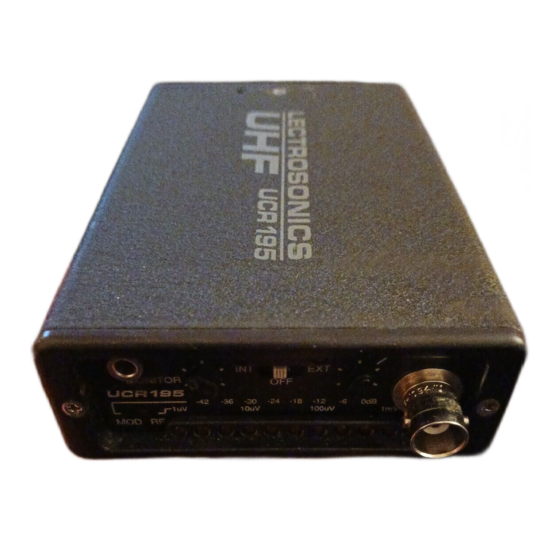
Page 8: Front Panel Controls And Functions
FRONT PANEL CONTROLS AND FUNCTIONS PWR LED MONITOR When lit, this LED indicates that power is applied to the This is a high quality audio output to drive a wide UCR195 and adequate voltage is present to operate the variety of different types of headphones. It is also unit. -
Page 9: Rear Panel Controls And Functions
Compact UHF Receiver REAR PANEL CONTROLS AND FUNCTIONS EXTERNAL POWER JACK The UCR195 can be powered from external 12 to 18 ment of the front panel Audio Output control. In the Volts DC applied directly to this jack, or conventional Low position the adjustment range is from –50dBm to –... -
Page 10: Antenna Use And Placement
The result would be a transmitter location. “drop-out.” A drop-out sounds like either audible noise Lectrosonics transmitters radiate power very efficiently, (hiss), or in severe cases, may result in a complete loss and the receivers are very sensitive. This reduces drop- of the carrier and the sound when the transmitter is outs to an insignificant level. -
Page 11: Operating Instructions
Compact UHF Receiver OPERATING INSTRUCTIONS 1. Connect the power cord or install the batteries. 2. Attach the antenna. 3. Connect the audio cable to the audio output XLR. 4. Set the front panel Audio Output Level control to minimum and set the Power switch to either Int or Ext, depend- ing upon the power source. -
Page 12: Troubleshooting
TROUBLESHOOTING POWER SUPPLY AND FUSE ANTENNAS AND RF SIGNAL STRENGTH LEDs not lit or dimly lit RF Level is weak. • Antenna is disconnected or there is a bad • AC power cord disconnected. connection • External power supply disconnected or •... -
Page 13: Returning Units For Repair
LECTROSONICS service department is equipped and staffed to quickly repair your equipment. In-warranty repairs are made at no charge in accordance with the terms of the warranty. Out of warranty repairs are charged at a modest flat rate plus parts and shipping. -
Page 14: Specifications And Features
SPECIFICATIONS AND FEATURES Receiver Operating Frequencies: 470 to 608 MHz, crystal controlled Monitor out: Front panel 3.5mm stereo mini jack – high level output for stereo Receiver Type: Dual conversion, superheterodyne or mono phones @ 32 Ohms or Frequency Stability: ±0.002 % higher –... - Page 15 Compact UHF Receiver Rio Rancho, NM – USA...
-
Page 16: Limited One Year Warranty
This warranty does not apply to used or demonstrator equipment. Should any defect develop, Lectrosonics, Inc. will, at our option, repair or replace any defective parts without charge for either parts or labor. If Lectrosonics, Inc. cannot correct the defect in your equipment, it will be replaced at no charge with a similar new item.
Need help?
Do you have a question about the UCR 195 and is the answer not in the manual?
Questions and answers