OHAUS Valor 2000 Service Manual
Hide thumbs
Also See for Valor 2000:
- Operating manual (41 pages) ,
- Instruction manual (19 pages) ,
- Service manual (49 pages)

Subscribe to Our Youtube Channel
Related Manuals for OHAUS Valor 2000


Summary of Contents for OHAUS Valor 2000
- Page 1 SERVICE MANUAL 2000 Valor ™ SCALES Ohaus Corporation, 7 Campus Drive, Suite 310, Parsippany, NJ 07054 (973) 377-9000...
- Page 3 ™ SCALES The information contained in this manual is believed to be accurate at the time of publication, but Ohaus Corporation assumes no liability arising from the use or misuse of this material. Reproduction of this material is strictly prohibited.
-
Page 5: Table Of Contents
Operational Test ......................4-1 Segment Display Test ....................4-1 4.4. Performance Tests ....................4-2 4.4.1 Precision Test ....................4-2 4.4.2 Repeatability Test .....................4-3 4.4.3 Linearity Test ....................4-5 4.4.4 Off-Center Load Test ..................4-5 4.4.5 Adjusting Off Center Load .................4-6 Ohaus Corporation www.ohaus.com Valor™ 2000 Series Service Manual... - Page 6 Power PCB housing, next to the rechargeable battery .........3-5 Gasket washers seal eight receptacles in Bottom Housing ........3-6 Segment Display ....................4-1 Scale drawing of Valor 2000 Load Cell and Weighing Pan ........4-4 Valor 2000 Scales: Housing & Internal Parts ............5-2 Valor™ 2000 Series Service Manual...
-
Page 7: Chapter 1 Getting Started
INTRODUCTION This service manual contains the information needed to perform routine maintenance and service on the Ohaus Valor 2000 Series scales. Familiarity with the scale’s Instruction Manual is assumed. The contents of this manual are contained in five chapters: Chapter 1 Getting Started – Contains information on service facilities, tools and test equipment, specifications, and the mechanical and electronic functions of the scale. -
Page 8: Tools And Test Equipment Required
TOOLS AND TEST EQUIPMENT REQUIRED The service shop should contain the following equipment: 1. Standard hand tools. 2. Digital Voltmeter (DVM). 3. Standard Electronics tool kit. 4. Grounding mat and clip. 5. Strain Gauge Simulator. Ohaus Corporation www.ohaus.com Valor™ 2000 Series Service Manual... -
Page 9: Specifications
CHAPTER 1 GETTING STARTED SPECIFICATIONS Complete specifications for the Ohaus Valor 2000 Scales are listed in Table 1-2. When a scale has been serviced, it must meet the specifications listed in the table. Before servicing the scale, determine what specifications are not met. -
Page 10: Scale Operation
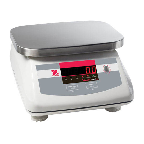
This section contains information on the basic operation of the scale. 1.5.1 OVERVIEW OF THE CONTROLS Figure 1-1. Valor 2000 Front Display: with controls. (The display and LEDs are duplicated on the rear of the scale, to facilitate customer viewing.) TABLE 1-2. -
Page 11: Power On
CHAPTER 1 GETTING STARTED 1.5.2 Power ON With power applied, press On/ >O/T< /Off. All segments will appear briefly followed by Ohaus, a software revision number, and then * 0.00 g. The scale can operate on either AC Power, with the included AC adapter, or on the internal rechargeable battery. -
Page 12: Menu Setup
CHAPTER 1 GETTING STARTED 1.5.4 Menu Setup Programmable features of the Valor 2000 scales are contained in menus which are accessed through the Display Panel’s control switches. See the Instruction Manual for a full description of the menus and how to access them. -
Page 13: Legal For Trade
LFT mode again. Local authorities may apply a seal as shown in Figure 1-4. Figure 1-4. LFT Lock Seal. Valor™ 2000 Series Service Manual Ohaus Corporation www.ohaus.com... - Page 14 CHAPTER 1 GETTING STARTED Ohaus Corporation www.ohaus.com Valor™ 2000 Series Service Manual...
-
Page 15: Chapter 2 Troubleshooting
If more than one symptom is observed, approach one area at a time, and remember that the symptoms may be interrelated. If a problem arises that is not covered in this manual, contact Ohaus Corporation for further information. Valor™ 2000 Series Service Manual... -
Page 16: Checking Load Cells For Trouble
The EXE+ and EXE– wires should be connected to the PCB, and the SIG+ and SIG– wires must be disconnected. Record the colors for each wire connection before disconnecting. (See Table 2-2 for typical color code for Valor 2000.) TABLE 2-2. COLOR CODE FOR LOAD CELL WIRING*... -
Page 17: Load Cell Output Readings (In Mv With 5V Excitation)
1 2 3 4 Load Cell Figure 2-1. Valor 2000 PCB connections NOTE: Table 2-3 indicates typical readings. Actual values can vary, but should remain linear throughout the range. If readings are out of tolerance, replace the Load cell. (See Section 3.6.) TABLE 2-3. -
Page 18: Testing The Printed Circuit Board (Pcb)
4. Measure incoming power from the AC Adapter Connector shown in Figure 2-1. The voltage should read between 9 and 14 volts dc with power off and above 9 Volts dc with power on. 5. Perform simulator testing. Ohaus Corporation www.ohaus.com Valor™ 2000 Series Service Manual... - Page 19 PCB is functional. If the scale readings vary, or do not agree with readings in Table 2-3, the Main PC Board is defective and should be replaced. (See Chapter 3.) Valor™ 2000 Series Service Manual Ohaus Corporation www.ohaus.com...
-
Page 20: Diagnostic Guide
Place platform on the balance. If the problem continues, add a small amount of weight at power on. If the problem persists, perform span and linearity calibration from Service menu. (See Appendix B.) Ohaus Corporation www.ohaus.com Valor™ 2000 Series Service Manual... -
Page 21: Chapter 3 Maintenance Procedures
5. Make a visual inspection for faulty connectors, wiring, and loose hardware. SERVICE STRATEGY All parts of the Valor 2000 or designed to be replaced rather than repaired. This includes the Main Printed Circuit Board (PCB), the Rear Display PCB, the Load Cell, the Power PCB, the Rechargeable Battery, and the cables that connect them. -
Page 22: Separating The Top And Bottom Housings
CHAPTER 3 MAINTENANCE PROCEDURES 3.3.1 Separating the Top and Bottom Housings Common hand tools are sufficient to disassemble the Valor 2000 scales. Turn the scale off and unplug the power cord before you begin. 1. Lift off the Weighing Pan from the Pan Support. -
Page 23: Removing The Component Covers And Lifting Out The Cable Plugs
6. Re-seat the white plastic Cable Tabs connecting the Power PCB and the Rear Display PCB to the Main PCB. 7. Position the PCB Cover over the screw holes, insert the eight screws and tighten them. 8. Re-insert the Cable Plugs in the PCB Cover. Valor™ 2000 Series Service Manual Ohaus Corporation www.ohaus.com... -
Page 24: Replacing The Rear Display Pcb
Load Cell Cover. Note: There is no need to remove the bolts in the metal bracket surrounding the Load Cell, unless it is necessary to adjust the Up/Down Stops. Ohaus Corporation www.ohaus.com Valor™ 2000 Series Service Manual... -
Page 25: Cable Set Replacement
CHAPTER 3 MAINTENANCE PROCEDURES Removing/Replacing the Power Supply PCB The Valor 2000’s power supply is located in the Power PCB Housing. To replace it: 1. Remove the four screws in its cover. 2. Lift the cover as much as possible to access and remove the white tabs holding the two cable sets to the PCB. -
Page 26: Replacing The Gaskets
Top Housing, before installing the Pan Support. Note the placement of the gasket-washers, as shown in Figure 3.4: Gasket washers seal screw holes in the Bottom Housing Figure 3.6. Gasket washers seal eight receptacles in Bottom Housing. Ohaus Corporation www.ohaus.com Valor™ 2000 Series Service Manual... -
Page 27: Setting/Removing Legal-For-Trade
CHAPTER 3 MAINTENANCE PROCEDURES 3.10 Setting/Removing Legal-For-Trade The Valor 2000 can be used in Legal-For-Trade (LFT) mode, after being inspected and sealed in accordance with local weights and measures or approval agency regulations. If the scale is serviced and the LFT seal is broken, it must be re-inspected and re-sealed to be used again in Legal-For-Trade mode. - Page 28 CHAPTER 3 MAINTENANCE PROCEDURES Ohaus Corporation www.ohaus.com Valor™ 2000 Series Service Manual...
-
Page 29: Chapter 4 Testing
4.1.1 TEST MASSES REQUIRED The masses required to test the Ohaus Valor 2000 scales must meet the requirements of ASTM Class 4 or OIML F2 Tolerance. The mass values are listed in Table 4-1. TABLE 4-1. TEST MASS VALUES... -
Page 30: Performance Tests
CHAPTER 4 TESTING Performance Tests Accurate performance of the Valor 2000 scales is determined by a series of four performance tests. The displayed readings are compared with the tolerances listed for each test in Table 1-2. Tolerance values are expressed in counts. A one-count difference is shown in the last digit on the scale display. -
Page 31: Repeatability Test
3. Remove the mass from the platform. 4. Repeat this test starting at Step 1 until you record a total of ten readings Fill in the worksheet (Table 4-2) with the ten (10) readings. Valor™ 2000 Series Service Manual Ohaus Corporation www.ohaus.com... -
Page 32: Repeatability Worksheet
Note: If the balance does not meet specifications, move it to a suitable location, ensure that it is level, and try again. If it still does not meet specifications, perform a service calibration, and try again. (See Appendix B for Service Calibration.) Ohaus Corporation www.ohaus.com Valor™ 2000 Series Service Manual... -
Page 33: Linearity Test
5. Maximum allowable change in displayed weight readings for each of the four positions can be found in Tables 1-2 (Specifications, page 1-3). If this maximum is exceeded, follow procedures in Section 4.4.5, Adjusting Off Center Load. Valor™ 2000 Series Service Manual Ohaus Corporation www.ohaus.com... -
Page 34: Adjusting Off Center Load
Weighing Pan’s center, with points A – D indicated Figure 4-2. Scale drawing of Valor 2000 Load Cell and Weighing Pan. 1. Place the test weight in the center of the Weighing Pan. 2. Tare the balance. 3. Move the weight to point A and record the reading. - Page 35 CHAPTER 5 PARTS LISTS & DIAGRAMS This section of the manual contains exploded views of the Valor 2000 scales. The exploded view drawings are designed to identify the parts which can be serviced on the scale in the field. NOTE: In all cases where a part is replaced, the scale must be thoroughly checked after the replacement is made.
-
Page 36: Valor 2000 Scales: Housing & Internal Parts
CHAPTER 5 PARTS LISTS & DIAGRAMS VALOR 2000 SCALES: HOUSING & INTERNAL PARTS Figure 5-1. Valor 2000 Scales: Housing & Internal Parts. Ohaus Corporation www.ohaus.com Valor™ 2000 Series Service Manual... -
Page 37: Valor 2000 Scales: Housing & Internal Parts
Battery, Rechargeable Hardware Kit LFT Sealing Kit Level Bubble Adapter Note: The Parts List is identical for all Valor 2000 models. For parts numbers, see your local Ohaus distributor, or visit www. Ohaus.com. Valor™ 2000 Series Service Manual Ohaus Corporation www.ohaus.com... - Page 38 CHAPTER 5 PARTS LISTS & DIAGRAMS Ohaus Corporation www.ohaus.com Valor™ 2000 Series Service Manual...
-
Page 39: Appendix A Standard Calibration Calibration
Weights and Measures authorities. 3. Allow the scale to warm up for approximately 20 minutes after stabilizing to room temperature. 4. To abort calibration, press the Exit button anytime during the calibration process. Valor™ 2000 Series Service Manual Ohaus Corporation www.ohaus.com... -
Page 40: Span Calibration
Then try to calibrate again. If it continues to fail, there may be an internal problem. To resolve internal problems, follow procedures in Chapter 3. Ohaus Corporation www.ohaus.com Valor™ 2000 Series Service Manual... -
Page 41: Linearity Calibration
The scale exits to the weighing mode and displays the actual weight value in the currently active unit of measure. (The example shows the WEIGH mode with the 3 kg linearity weight on the pan.) Valor™ 2000 Series Service Manual Ohaus Corporation www.ohaus.com... - Page 42 APPENDIX A STANDARD CALIBRATION Ohaus Corporation www.ohaus.com Valor™ 2000 Series Service Manual...
-
Page 43: Appendix B Service Calibration
Note: The available settings are 3, 6, and 15. The default setting is 3. Press NO to step through the settings. Press YES to accept the setting and move to the Service Unit menu item. Valor™ 2000 Series Service Manual Ohaus Corporation www.ohaus.com... -
Page 44: Service Unit Menu
The Ounce Unit menu item setting appears, blinking. The available settings are Off and On. The default is On. Press NO to step through the settings. Press YES to accept the setting and move to the Service Calibration menu. Ohaus Corporation www.ohaus.com Valor™ 2000 Series Service Manual... -
Page 45: Service Span Calibration
If span calibration was successful, the actual weight reading appears for three seconds, followed by the Service Linearity Calibration menu item. (The example shows a 3 kg span weight on the pan.) Valor™ 2000 Series Service Manual Ohaus Corporation www.ohaus.com... -
Page 46: Service Linearity Calibration
Then try to calibrate again. If it continues to fail, there may be an internal problem. To resolve internal problems, follow procedures in Chapter 3. Ohaus Corporation www.ohaus.com Valor™ 2000 Series Service Manual... - Page 48 *80252589* P/N 80252589B SERVICE MANUAL: Valor 2000 SERIES SCALES...
Need help?
Do you have a question about the Valor 2000 and is the answer not in the manual?
Questions and answers