
Related Manuals for OTS FTD100Micro-SST


Summary of Contents for OTS FTD100Micro-SST
-
Page 1: Installation And Operation Manual
FTD100Micro Series Installation & Operation Manual Installation and Operation Manual FTD100Micro Series 8-bit Digital Series 1-ch Video Fiber Optic Converter OT Systems Ltd., 2014 Rev 1.2 www.ot-systems.com... - Page 2 FTD100Micro Series Installation & Operation Manual Models covered in this manual Single-Mode Transmitters FTD100Micro-SST FTD100Micro-SSTL Single-Mode Receivers FTD100Micro-SSR FTD100Micro-SSRL Multi-Mode Transmitters FTD100Micro-SMT Multi-Mode Receivers FTD100Micro-SMR Compatible with the following Series: FTD100 FTD100M FTD100-XXR3 Remark: If the optical connector is FC type, the suffix in the model number will be “-FXX”. Eg.
-
Page 3: Table Of Contents
FTD100Micro Series Installation & Operation Manual Table of Contents SAFETY INSTRUCTIONS ..........................4 PRODUCT OVERVIEW ............................ 5 ..............................5 NTRODUCTION ............................5 ODELS SELECTION TABLE INSTALLATION..............................6 ................................6 ENERAL ............................6 ICRO UNIT INSTALLATION CABLE CONNECTIONS & SETUP PROCEDURES ....................7 .......................... -
Page 4: Safety Instructions
FTD100Micro Series Installation & Operation Manual (1) Safety Instructions Please be familiar with all information in this manual prior to installation and operation. Note 1: The products described contain a Class 1 laser or LED fiber optic emitter. The following safety precautions apply. -
Page 5: Product Overview
The Micro unit comes with an external power supply FT-PA/12V, which can be powered by local 110/220V power. 2.2 Models selection table Installation Model Description Remarks requirements FTD100Micro-SST Single-mode 1-Ch Video Transmitter Horizontally or FT-PA/12V Micro Unit vertically external wall-mounted... -
Page 6: Installation
FTD100Micro Series Installation & Operation Manual (3) Installation 3.1 General All OT Systems products are thoroughly inspected, tested and securely packaged before delivery to ensure a stable, intact and trouble-free service. Please check the equipment upon receipt for any visible damage which may have been caused during shipping. The FTD100Micro Series (Fig. -
Page 7: Cable Connections & Setup Procedures
FTD100Micro Series Installation & Operation Manual (a) Installation (b) Side view of the clip (c) Side view of the Micro unit pushed into the clip Fig. 3.3 Micro unit installation on the clip Connect all the signal inputs and outputs at the back of the unit with appropriate cables: fiber optic cable for optical link, BNC cable for video input/output (Tx/Rx). -
Page 8: Ground Connections
FTD100Micro Series Installation & Operation Manual Typical System Cable Connections Diagram: Micro Transmitter Micro Receiver Fig 4.1 Micro to Micro unit connection diagram 4.2 Ground connections For enhanced safety to reduce the risks of electrical shock and physical damage, caused by lightning and other power surges, as well as a connection to the surge suppresion devices in the product, a screw terminal is provided on the Micro cabinets (Fig. -
Page 9: Operational Guides
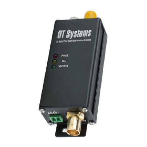
FTD100Micro Series Installation & Operation Manual (5) Operational Guides 5.1 FTD100Micro Series Transmitter LED Indicators Indicator Colour Description Lit when power is supplied to the Transmitter. Yellow Lit when optical signal from receiver to transmitter is active.* VIDEO IN / VIN Green Lit when video signal is fed into the VDEO IN connector. -
Page 10: Specifications
FTD100Micro Series Installation & Operation Manual (6) Specifications MODELS* FTD100Micro-SST(R) FTD100Micro-SST(R)L FTD100Micro-SMT(R) PARAMETERS (Single-Mode) (Single-Mode) (Multi-Mode) OPTICAL No. of Fiber / Connector 1 / ST(or FC) 1 / ST(or FC) 1 / ST(or FC) Wavelength 1310 nm 1310 nm 1310 nm... -
Page 11: Drawings
FTD100Micro Series Installation & Operation Manual (7) Drawings Fig. 7.1 Dimensional drawings of Micro unit (mm) (8) Warranty Information All OT Systems FT Series products are subject to a limited life-time warranty offered by the company in normal circumstances. Please refer to the OT Systems Products Warranty Statement for details.
Need help?
Do you have a question about the FTD100Micro-SST and is the answer not in the manual?
Questions and answers