
Related Manuals for OTS FT800-SSTSA


Summary of Contents for OTS FT800-SSTSA
-
Page 1: Installation And Operation Manual
FT800 Series Installation & Operation Manual Installation and Operation Manual FT800 Series 10-bit Digital Series 8-ch Video Fiber Optic Converter OT Systems Ltd., 2014 Rev 1.2 www.ot-systems.com... - Page 2 FT800 Series Installation & Operation Manual Models covered in this manual Standalone Units Card Modules Single-Mode Transmitters Single-Mode Transmitters FT800-SSTSA FT800-SST FT800-SSTLSA FT800-SSTL Single-Mode Receivers Single-Mode Receivers FT800-SSRSA FT800-SSR FT800-SSRLSA FT800-SSRL Multi-Mode Transmitter Multi-Mode Transmitter FT800-SMTSA FT800-SMT Multi-Mode Receiver Multi-Mode Receiver...
-
Page 3: Table Of Contents
FT800 Series Installation & Operation Manual Table of Contents SAFETY INSTRUCTIONS ..........................4 PRODUCT OVERVIEW ............................ 5 ..............................5 NTRODUCTION ............................6 ODELS SELECTION TABLE INSTALLATION..............................7 ................................7 ENERAL ..........................7 TANDALONE UNIT INSTALLATION ........................... 8 ARD MODULE INSTALLATION CABLE CONNECTIONS &... -
Page 4: Safety Instructions
FT800 Series Installation & Operation Manual (1) Safety Instructions Please be familiar with all information in this manual prior to installation and operation. Note 1: The products described contain a Class 1 laser or LED fiber optic emitter. The following safety precautions apply. -
Page 5: Product Overview
FT800 Series Installation & Operation Manual (2) Product Overview 2.1 Introduction The FT800 Series products comprise of either single-mode or multi-mode fiber optic transmitters and receivers for the optical transmission of EIGHT forward (Tx → Rx) video singals on one fiber. The products work at wavelengths of 1310nm or 1550nm with either a 9/125um or 62.5/125um fiber for single-mode or multi-mode transmission respectively. -
Page 6: Models Selection Table
FT800 Series Installation & Operation Manual 2.2 Models selection table Installation Models Descriptions Remarks requirements FT800-SSTSA Single-mode 8-Ch. Video Transmitter Horizontally or FT-PA/12V Standalone Unit vertically external wall-mounted power FT800-SSTLSA Single-mode Long-haul 8-Ch. Video Transmitter Standalone Unit Standalone supply is... -
Page 7: Installation
FT800 Series Installation & Operation Manual (3) Installation 3.1 General All OT Systems products are thoroughly inspected, tested and securely packaged before delivery to ensure a stable, intact and trouble-free service. Please check the equipment upon receipt for any visible damage which may have been caused during shipping. The FT800 Series standalone units (Fig. -
Page 8: Card Module Installation
FT800 Series Installation & Operation Manual 3.3 Card module installation Insert the card module into the FT-C18 chassis along the top and bottom card guides of an empty slot and push the card into the multi-pin socket at the rear firmly. Secure with the provided thumb screws. - Page 9 FT800 Series Installation & Operation Manual Standalone Transmitter Card Module Receiver Fig 4.2 Standalone unit to Card Module connection diagram Card Module Transmitter Card Module Receiver Fig 4.3 Card Module to Card Module connection diagram www.ot-systems.com...
-
Page 10: Ground Connection
FT800 Series Installation & Operation Manual 4.2 Ground connection For enhanced safety to reduce the risks of electrical shock and physical damage, caused by lightning and other power surges, as well as a connection to the surge suppresion devices in the product, a screw terminal is provided on the Standalone cabinets (Fig. -
Page 11: Ft800 Series Receiver
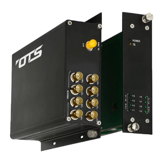
FT800 Series Installation & Operation Manual Signal Ports OPT - ST (or FC) Optical Connector for fiber cable connection. VIDEO IN - BNC Video Connectors for video signal inputs. 5.2 FT800 Series Receiver LED Indicators Indicator Color Description Lit when power is supplied to the Receiver. Yellow Lit when optical signal from transmitter to receiver is active. -
Page 12: Specifications
FT800 Series Installation & Operation Manual (6) Specifications MODELS* FT800-SST(R)SA FT800-SST(R)LSA FT800-SMT(R)SA FT800-SST(R) FT800-SST(R)L FT800-SMT(R) PARAMETERS (Single-Mode) (Single-Mode) (Multi-Mode) OPTICAL No. of Fiber / Connector 1 / ST (or FC) 1 / ST (or FC) 1 / ST (or FC) Wavelength 1310 nm 1550 nm... -
Page 13: Drawings
FT800 Series Installation & Operation Manual (7) Drawings Fig. 7.1 Dimensional drawings of Standalone unit (mm) (8) Warranty Information All OT Systems FT Series products are subject to a limited life-time warranty offered by the company in normal circumstances. Please refer to the OT Systems Products Warranty Statement for details. -
Page 14: Contact Information
FT800 Series Installation & Operation Manual (9) Contact Information APAC Operation EMEA Operation AMERICAS Operation Address: Address: Address: Unit 1023, 10/F, Landmark J. Slovackio str. 4, LT-11107, 18 West Main Street, Plano, North, 39 Lung Sum Avenue, Vilnius, Lithuania IL 60545, U.S.A. Sheung Shui, N.T., Hong Kong Tel: (852) 2672 5153 Tel: (370) 60730087...
Need help?
Do you have a question about the FT800-SSTSA and is the answer not in the manual?
Questions and answers