
Related Manuals for Supero SC512C Series


Summary of Contents for Supero SC512C Series
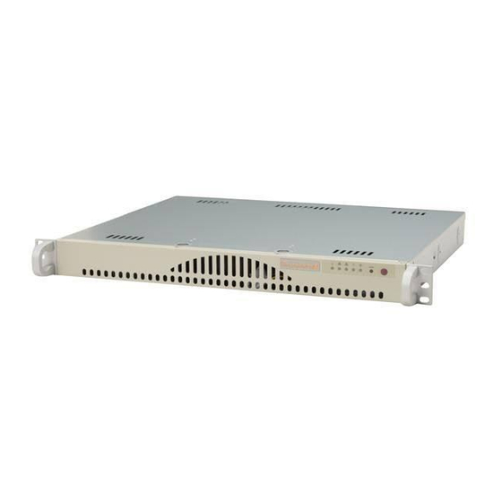
- Page 1 ® UPER The SC512C/L Series The SC512C Series The SC512L Series SC512 CHASSIS USER'S GUIDE...
- Page 2 Clara County in the State of California, USA. The State of California, County of Santa Clara shall be the exclusive venue for the resolution of any such disputes. Supermicro's total liability for all claims will not exceed the price paid for the hardware product.
-
Page 3: Table Of Contents
A. Important Safety Guidelines ... 2-4 B. Tools Needed ... 2-4 C. Removing the Top Chassis Cover and the HDD Tray Bracket ... 2-5 D1. Removing the CD-ROM Module ... 2-6 D2. Removing the HDD Drive Tray Housing and Installing the HDDs ... 2-7 E Installing the Motherboard ... -
Page 4: Chapter 1- Introduction
Keep all components and printed circuit boards (PCBs) in their antistatic bags until ready for use. • Touch a grounded metal object before removing chassis components or the motherboard from the antistatic bag. • Do not let components or PCBs come into contact with your clothing, which may retain a charge even if you are wearing a wrist strap. -
Page 5: General Safety Guidelines
Avoid wearing loose clothing to preventing it from coming into contact with electrical circuits or being pulled into a cooling fan. • The handles are for sliding the chassis in and out of the racks only. Do not carry the chassis by the handles. 1-4. Operation Safety Guidelines Warning: For proper cooling, make sure to install all chassis covers before turning on the system. -
Page 6: Product Compliance Information
SC512 Chassis User’s Guide 1-6 Product Compliance Information If integrated with a motherboard validated and recommended by Supermicro, and confi gured based upon the instructions outlined in this manual, the SC512 Chassis is compliant with the following safety standards/requirements: Product Safety... -
Page 7: Packing List And The Sc512 Specifi Cations
Power 200W The SC512L-260 Series: Component Blower One (5000rpm blower) Two 3.5” Drives Floppy CD-ROM Power 260W The SC512C Series: Component Blower One (3800rpm blower) One 3.5” Drive One 2.0 Connection Floppy One Slim FDD CD-ROM One Slim CD-ROM Power... -
Page 8: The Accessory Kit
CPU Support Pentium 4 Expansion Card One full-height/half-length PCI Slot (w/Riser Card) Drive Bays The SC512L Series: two 3.5” fixed, the SC512C Series: one 3.5 fixed Cooling System One 10cm blower (200W: 3800rpm, 260W: 5000rpm) Front Panel LEDs One PWR LED, one HDD Activity LED, two Network... -
Page 9: Chapter 2: Chassis Description And Installation Procedures
Chapter 2: Chassis Description and Installation 2-1 Chassis Description A. Contents of the Accessory Kit: The following items are included in the Accessory Kit: A. A. DRIVE DRIVE B. B. E. E. J. J. RAIL (*Not included in the shipment) RAIL (*Not included in the shipment) H. -
Page 10: Chassis Front View And The Front Control Panel
The SC512L Chassis Front View 1. Front Panel and I/O Device Defi nitions 1. Front Panel LED Indicators 2. I/O Devices (SC512C: 1 CD-ROM and 1 HDD, SC512L: 1 CD-ROM only) 3. USB ports (x2) 2. Front Panel LED Button Defi nitions 1a. -
Page 11: Chapter 2: Chassis Description And Installation Instructions
Chapter 2: Chassis Description and Installation Instructions D. Chassis Rear View SC512 Chassis Rear View 1. Back Panel and I/O Device Descriptions 1. Power Connector 2. COM Port 3. LAN Ports... -
Page 12: Chassis Installation
Removing the chassis covers: After completing the above steps, you can remove the chassis covers and install components and devices into the chassis as described in this chapter. 1. Unlock and remove the screws and fasteners to remove the cover or compo- nents. -
Page 13: Removing The Top Chassis Cover And The Hdd Tray Bracket
C. Removing the Top Chassis Cover and the HDD Tray Bracket from the chassis Before installing a hard drive into the chassis, you need to remove the top (*Note: Removing the cover and the HDD tray bracket from the chassis. -
Page 14: D1. Removing The Cd-Rom Module
SC512 Chassis User’s Guide D1. Removing the CD-ROM Module Before installing a CD-ROM into the CD-ROM module, you need to remove the CD-ROM module from the chassis. Procedures 1. Remove the screw. 2. Once the screw is removed, slide the CD-ROM module toward the backplane to loosen it as shown in the picture below. -
Page 15: D2. Removing The Hdd Drive Tray Housing And Installing The Hdds
After the HDD Drive Tray Bracket is removed from the chassis, you can install HDDs into the HDD Drive Housing. Procedures 1. Remove the four screws on the back of the chassis as shown in the picture. 2. Once the screws are removed, you can remove the HDD tray from the chas- sis. -
Page 16: E Installing The Motherboard
SC512 Chassis User’s Guide E. Installing the Motherboard Be sure to disconnect the power supply before accessing or installing the motherboard into the chassis. (Refer to Chapter 1 for Safety Guidelines.) Procedures 1. Lay the chassis on a fl at surface. -
Page 17: Installing And Uninstalling The Heatsink Mechanism
Chapter 2: Chassis Description and Installation Instructions F. Installing and Uninstalling the Heatsink Mechanism Heatsinks are heavy. Please handle with care!! *Note: Be sure to use Heatsink # SNK-P0011 for a UP system, and use Heatsink #SNK-P0007 for a DP System. -
Page 18: Installing The Cooling Fan Module And The Air Shroud
Procedures (*Installing the Air Shroud) After the fan module has been properly installed in the chassis, you will need to install the air shroud for proper cooling. 4. Locate the two holes on the air shroud and the two pins on the fan module. -
Page 19: Installing Chassis Rails
H. Installing Chassis Rails (*Optional) (*Note: if your chassis does not come with chassis rails, please follow the procedure listed on the last page to install the SC512 directly into the rack.) Please make sure that the chassis covers and chassis rails are... - Page 20 4. Attach an inner rail to each side of the chassis and secure the inner rail to the chassis by inserting three Type G screws through the holes on each side of the chassis and the inner rail.
-
Page 21: I-1. Installing The Traditional Up Racks
Chapter 2: Chassis Description and Installation Instructions I-1 Installing the Traditional UP Racks (*Optional) After you have installed the inner rails on the chassis, you are ready to install the outer rails of rail assemblies to the rack. (* The rails are designed to fi t in the racks with the depth of 28" to 33".) Procedures 1. - Page 22 Some adjustment to the slide assemblies might be needed for easy instal- lation.) 8. You will need to release the safety taps on both sides of the chassis in order to completely remove the chassis out of the rack.
-
Page 23: I-2. Installing The Open Racks
Chapter 2: Chassis Description and Installation Instructions I-2 Installing the Open-Racks (*Optional) After you have installed the inner rails on the chassis, you are ready to install the outer rails of rail assemblies to the rack. (* The rails are designed to fi t in the racks with the depth of 28" to 33".) Procedures 1. - Page 24 SC512 Chassis User’s Guide 3. Attach the front (-short) bracket to the front end of the rack, and secure it to the rack with two Type H screws and Type I washers as shown below. 4. Attach the rear (-long) bracket to the rear end of the rack, and secure it to the rack with two Type H screws and Type I washers as shown below.
- Page 25 5. Measure the depth of your rack and adjust the length of the rails accordingly. Then, secure the rails to the chassis with Type G screws. 6. Slide the inner rails which are attached to the chassis into the outer rails on the rack.
- Page 26 1. Make sure that the rack is securely anchored onto a unmovable surface or structure before installing the chassis into the rack. 2. Unplug the power cord(s) of the rack before installing the chassis into the rack. 3. Make sure that the system is adequately supported. Make sure that all the com- ponents are securely fastened to the chassis to prevent components falling off from the chassis.
Need help?
Do you have a question about the SC512C Series and is the answer not in the manual?
Questions and answers