
Related Manuals for Yardworks 270-1241


Summary of Contents for Yardworks 270-1241
-
Page 1: Lawn Mower
OPERATOR’S MANUAL 18" Cordless Self-propelled Lawn Mower Item No . 270-1241 IMPORTANT: Read safety rules and instructions carefully before operating equipment. For parts or service, please call toll free helpline at 1-888-266-7096... -
Page 2: Table Of Contents
CONTENTS Contents ..........................2 ......................2 Safety information ......................3-8 Symbols .......................... 9-10 Battery & Charger ......................11-12 Know your lawn mower ...................... 13 Assembly ........................14-17 Operation ........................18-22 Maintenance ......................... 23-24 Storage ..........................25 Environmentally safe battery disposal ................26 Service .......................... -
Page 3: Safety Information
SAFETY INFORMATION IMPORTANT SAFETY INSTRUCTIONS I M P O R T A N T READ AND UNDERSTAND ALL INSTRUCTIONS. Failure to follow all instructions listed below • liquids, gases, or dust. Power tools create sparks which may ignite the dust or fumes. •... - Page 4 SAFETY INFORMATION • Do not use with damaged cord or plug. If appliance is not working as it should, has been dropped, damaged, left outdoors, or dropped into water, return it to a service center. • Removing the battery when not in use, before servicing, and before storing the tool. Such preventative safety measures reduce the risk of starting the tool accidentally.
- Page 5 SAFETY INFORMATION GENERAL OPERATION Use of this mower should be restricted to individuals who have read and understoood and will follow the warningsand instructions that are printed in this manual and on the mower. • Carefully read all instructions on the mower and in the manual before attempting to assemble and operate the mower.
- Page 6 SAFETY INFORMATION • • Stop the blade when crossing gravel driveways, walkways, or roads. • If the mower starts to vibrate excessively, stop the motor and check for the cause immediately. Vibrationis generally a warning of trouble. • Stop the motor and wait until the blade comes to a complete stop before removing the grass catcher or unclogging the chute.
- Page 7 BATTERY & CHARGER C A U T I O N : USE ONLY YARDWORKS APPROVED REPLACEMENT BATTERIES. OTHER BATTERIES MAY CAUSE INJURY OR DAMAGE TO THE MOWER. The battery that is supplied with this mower is a maintenance-free, sealed, 24 V storage battery.
- Page 8 SAFETY INFORMATION PROPER CARE FOR BATTERY Off-Season storage In order to ensure optimal performance, it is recommended that the battery be charged every two weeks when not in use. If all of the following conditions are met, the mower can be stored with the charger disconnected . 1.
-
Page 9: Symbols
SYMBOLS Some of the following symbols may be used on this product. Please study them and learn their meaning. Proper interpretation of these symbols will allow you to operate the product better and safer. SYMBOL NAME DESIGNATION/EXPLANATION Volts Voltage Amperes Current Hertz Frequency (cycles per second) -
Page 10: Symbols
SYMBOLS The following signal words and meanings are intended to explain the levels of risk associated with this product. SYMBOL SIGNAL MEANING DANGER Indicates an imminently hazardous situation, which, if not avoided, will result in death or serious injury. WARNING Indicates a potentially hazardous situation, which, if not avoided, could result in death or serious injury. -
Page 11: Battery & Charger
BATTERY & CHARGER CHARGING PROCEDURE NOTE: The battery can be charged in or out of the mower. The charger that is supplied with this mower is a specially designed 2-stage charger. Step 1: The red light will light up during the recharge cycle. Step 2: The green light will light up when the battery is fully charged. - Page 12 BATTERY & CHARGER BATTERY USE NOTE: If the switch does not re-engage or the mower does not run when the battery is installed, contact the toll free helpline 1-888-266-7096. BATTERY CAPACITY INDICATORS Push the Battery Capacity Indicator (BCI) switch, which is located on the back of the battery. The lights will indicate the battery's capacity, according the following chart.
-
Page 13: Know Your Lawn Mower
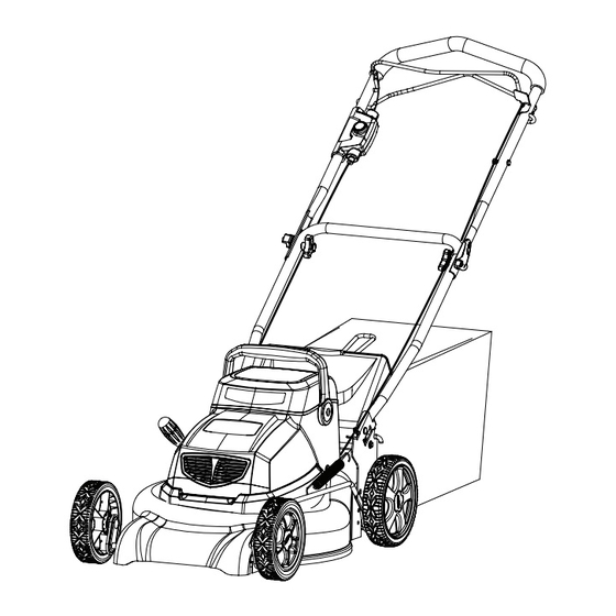
KNOW YOUR LAWN MOWER Read this operator's manual and safety rules before operating your lawn mower. Compare the illustration in Figure 1 to your lawn mower in order to familiarize yourself with the location of various controls and adjustments. Save this manual for future reference. Upper Bail Lower Bail... -
Page 14: Assembly
ASSEMBLY INSTRUCTIONS UNPACKING This product has been shipped completely assembled. • Carefully remove the product and any accessories from the box. Make sure that all items listed in the packing list are included. • Inspect the product carefully to make sure no breakage or damage occurred during shipping. •... -
Page 15: Assembly Instructions
ASSEMBLY INSTRUCTIONS W A R N I N G Do not allow familiarity with this product to make you careless. Remember that a careless W A R N I N G Always wear safety goggles or safety glasses with side shields when operating power tools. Failure to do so could result in objects being thrown into your eyes, resulting in possible serious injury. - Page 16 ASSEMBLY INSTRUCTIONS INSTALLING THE GRASS CATCHER BAG (See Figure 3) • Lift the chute cover (1). • Lift the grass catcher by its handle (2) and place under the chute cover so that the hooks (3) on the grass catcher frame are seated into the slots in the handle bracket. •...
-
Page 17: Assembly
ASSEMBLY INSTRUCTIONS INSTALLATION OR REMOVAL OF THE MULCH PLUG (See Figure 4) • REMOVE THE BATTERY, AND WAIT FOR BLADE TO COME TO A COMPLETE STOP. • To remove the mulch plug lift the chute cover (1) and pull out on the handle. •... - Page 18 OPERATING YOUR LAWN MOWER STARTING/STOPPING THE MOWER (See Figure 5) STARTING THE MOWER: • Press and hold the start button (1). • Pull the upper bail (2) toward the handle to start the mower. • Release the button (1). STOPPING THE MOWER: •...
-
Page 19: Operating Your Lawn Mower
OPERATING YOUR LAWN MOWER CUTTING HEIGHT ADJUSTMENT (See Figure 6) • Simply depress the lever (1) towards the wheel and move to desired position. This sets all wheels to the same position. • To raise the height, pull the height adjustment lever from the current stop position towards the back of the mower. - Page 20 OPERATING YOUR LAWN MOWER ADJUST THE UPPER HANDLE HEIGHT (See Figure 7) • Loosen the upper handle knob. • Adjust the upper handle to the most comfortable of the 2 positions. • Snug the upper handle knob and lock the cam lock handle to secure. Cam lock handle Upper handle knob Lock...
-
Page 21: Operation
OPERATING YOUR LAWN MOWER SLOPE OPERATION W A R N I N G Do not mow a slope that has an angle of greater than 15° (a rise of approximately 2-1/2 ft. [75 m] every 10 ft. [3 m]). Mow across the face of a slope, and never up and down. •... - Page 22 OPERATING YOUR LAWN MOWER MOWING TIPS NOTE: A sharp blade will greatly enhance the performance of the mower, especially when cutting high grass. Be sure to check the blade and to sharpen it at least once per year, as described in the Maintenance section. •...
-
Page 23: Maintenance
MAINTENANCE CUTTING BLADE REPLACEMENT (See Figure 8-9) W A R N I N G Always protect your hands by wearing heavy gloves and/or wrapping the cutting edges with rags or other materials when performing any maintenance on the blades. • RELEASE THE BAIL SWITCH TO TURN THE MOWER OFF, WAIT FOR THE BLADE TO COME TO A COMPLETE STOP, AND THEN UNPLUG THE POWER CORD. - Page 24 MAINTENANCE CLEAN THE MOWER W A R N I N G To reduce the risk of electric shock, do not expose the mower to water. p i l t r i and other debris will accumulate causing rust and corrosion. •...
-
Page 25: Storage
STORAGE The following steps should be taken to prepare the lawn mower for storage. • Follow Charging procedure carefully, ensure battery is fully charged before storing and charge every two weeks even when not in use. • Clean mower as instructed in previous section. •... -
Page 26: Environmentally Safe Battery Disposal
ENVIRONMENTALLY SAFE BATTERY DISPOSAL The following toxic and corrosive materials are in the batteries used in this battery pack: a toxic material. W A R N I N G the environment. Dispose of batteries according to local by-laws because this Lead-acid batteries contain lead and sulphuric acid that are hazardous materials. -
Page 27: Service
SERVICE • When ser vicing the mower, use only replacement par ts that are available from the manufacturer. In order to obtain replacement parts, call the toll-free helpline, at 1-888-266- 7096. The use of parts that do not meet the original equipment specifications may lead to improper performance, and may compromise safety. -
Page 28: Troubleshooting
TROUBLESHOOTING PROBLEM POSSIBLE CAUSE SOLUTION Handle not in Carriage bolts not seated Adjust the height of the handle and make position. properly. sure the carriage bolts are seated properly Handle knobs not tightened. Tighten handle knobs. Mower not starting. Battery is low in charge. Charge the battery. -
Page 29: Warranty
LIMITED TW O-YEAR WARRANTY • The manufacturer warrants to the original purchaser that each new product and service part is free from defects in material and workmanship and agrees to repair or replace under this warranty any defective product or part as follows from the original date of purchase. •... -
Page 30: Exploded View
EXPLODED VIEW... -
Page 31: Exploded View
EXPLODED VIEW... -
Page 32: Parts List
PARTS LIST ITEM NO. PART NO. DESCRIPTION Cable assy. 33304250-1 Upper bail 34115250 Foam 33305250-1 Lower bail 3220439 Nut M5 33323250 Bail stop 32208234 Bolt M5*30 33303250 Upper handle 32204234 Bolt M6*35 3220537 Nut M6 31901469-1 Drive cable 31102467 Cam lock assy. 34203229B Wheel cover (7”) 3411135... - Page 33 PARTS LIST ITEM NO. PART NO. DESCRIPTION 3290135 Cotter pin 33901234-1 Front wheel axle 33903234-1 Rear wheel axle 33908234 Housing 32101234 Bearing 32902234 Clip Ø26 32905234 Clip Ø10 32908234 Flat washer 33204234 Gear pinion 32906234-1 33302234 Link bar 31103473 Transmission 33318234 Extension spring 32902250...
-
Page 34: Parts List
PARTS LIST ITEM NO. PART NO. DESCRIPTION 31102482 Battery assy. 72-1 3220345 Screw 72-2 34104229 Battery Housing 72-3 3220204 Screw ST4*8-C 72-4 36501229 Rubber cover for connector 72-5 3660239 2 X 12 V 20Ah SLA BATTERY 72-6 36502229 Connector terminal 72-7 3050245 Wire (blue)
Need help?
Do you have a question about the 270-1241 and is the answer not in the manual?
Questions and answers