Table of Contents
Advertisement
Quick Links
Advertisement
Table of Contents

Related Manuals for AirLive DS-100


Summary of Contents for AirLive DS-100
- Page 1 DS-100 Signal bridge between RJ-45 and RS-232 User’s Manual Version 2.0...
- Page 2 OvisLink Corp. has made the best effort to ensure the accuracy of the information in this user’s guide. However, we are not liable for the inaccuracies or errors in this guide. Please use with caution. All information is subject to change without notice All Trademarks are properties of their respective holders. AirLive DS-100 User’s Manual...
-
Page 3: Table Of Contents
3.4.1 Welcome Screen and Login ............... 14 3.5 Introduction to Web Management ............ 15 3.5.1 Getting into Web Management ..............15 4. Web Management in DS-100 ..............16 4.1 About DS-100 Menu Structure ............16 4.2 System Configuration ..............17 4.2.1 DS-100 Configuration ................ -
Page 4: Introduction
Pre-integrated with the Controller/Gateway so that account generation becomes quick and easy to the operator, simply by a push of buttons on the device. It provides DS-100 and a POS printer as a combo set called Network Ticket Generator. The followings are typical application scenarios:... - Page 5 Gateway, and a Network Ticket Generators set. The Gateway alone serves as an AP and a gateway, Network Ticket Generator enables the registration operator to generate and issue accounts via push buttons on the DS-100 and hand out the account ticket printed out by POS printer.
- Page 6 POS printers, it can also be deployed independently to connect other RS232 devices to an Ethernet network for remote operation. If you will be deploying DS-100 independently to manage other serial devices, please carefully set the Serial Settings in DS-100 to match the operating needs of your serial device.
-
Page 7: How To Use This Guide
FAQ are frequently updated with latest information. In addition, you might find new firmwares that either increase software functions or provide bug fixes for DS-100. You can reach our on-line support center at the following link: http://www.airlive.com/support/support_2.jsp Since 2009, AirLive has added the “Newsletter Instant Support System” on our website. -
Page 8: Features
Trigger the Built-in On-Demand Billing Plan inside the M-series Controller n Flow Control: RTS/CTS and DTR/DSR (RS-232 only), XON/XOFF n Supports Network Protocols: ICMP, IP, TCP, UDP, DHCP, BOOTP, Telnet, SNMP, HTTP n Web Management via web browser AirLive DS-100 User’s Manual... -
Page 9: Installing The Ds-100
One unit of DS-100 Power Adapter User Guide (CD-ROM) Quick Installation Guide Compare the contents of your DS-100 package with the standard checklist above. If any item is missing or damaged, please contact your local dealer for service. AirLive DS-100 User’s Manual... -
Page 10: Knowing Your Ds-100
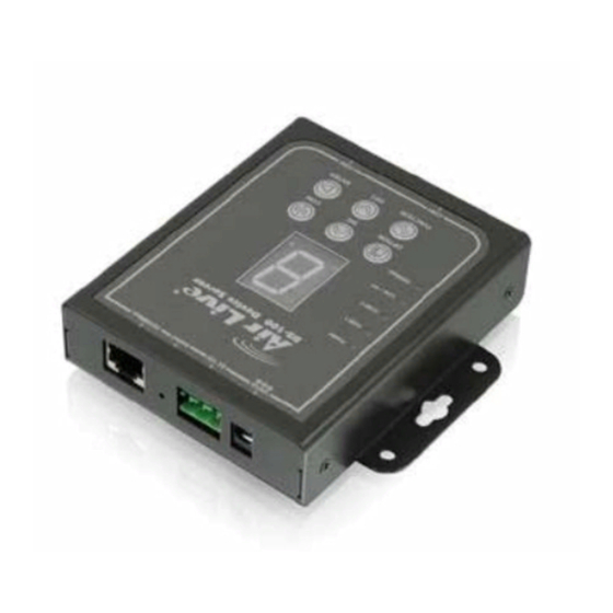
2. Installing the DS-100 2.3 Knowing your DS-100 Below are descriptions and diagrams of the product: Top Panel LED Behavior The power socket for connecting to an Adapter Socket external power source through the power (12V/1A) adapter provided in the package. - Page 11 2. Installing the DS-100 Bottom Panel COM 1 Serial Port for connection with a POS printer. Serial Port for connection with a POS printer. COM2 Used for back up when COM 1 malfunctions. Main Panel OPTION For future use. Increase the numeric display for selecting a billing plan number.
-
Page 12: Hardware Installation
Create and print out an account for the ENTER chosen billing plan. 2.4 Hardware Installation The following diagram illustrates how to connect DS-100 to the POS printer and Gateways/Controllers. Please follow the steps described below to install hardware: AirLive DS-100 User’s Manual... -
Page 13: Led Indicator
(2) Attach POS printer to a power source, through adaptors provided in the package and turn on the power switch situated on the left side of the device. (3) Connect POS printer to the COM1 port of DS-100 by a RS-232 cable provided within POS printer package. - Page 14 2. Installing the DS-100 Power Turned on when properly connect to power supply. Turned on when output is switched to COM1. * Note: When COM 1 and COM 2 are blinking simultaneously, this means that Terminal Server configuration is not set COM 1 correctly.
-
Page 15: Configuring The Ds-100
The default Gateway is: 192.168.1.254 3.2 Prepare your PC The DS-100 can be managed remotely by a PC through RJ-45 cable. The default IP address of the DS-100 is 192.168.1.10 with a subnet mask of 255.255.255.0. This means the IP address of the PC should be in the range of 192.168.1.2 to 192.168.1.253 (do not include 192.168.1.10). -
Page 16: Management Interface
The DS-100 can be configured using on the Web management interfaces. Web Management (HTTP): You can manage your DS-100 by simply typing its IP address in the web browser. Most functions of DS-100 can be accessed by web management inter face. We recommend using this interface for initial configurations. -
Page 17: Introduction To Web Management
3. Configuring the DS-100 3.5 Introduction to Web Management We recommend users to browse through DS-100’s web management interface to get an overall picture of the functions and interface. Below are the recommended initial configurations for first time login: * Note: By default, IE5.0 or later version does not allow Java Applets to open sockets. The user has to explicitly modify the browser setting to enable Java Applets to use network ports. -
Page 18: Web Management In Ds-100
In this chapter, we will explain all settings in web management interface. Please be sure to read through Chapter 3’s “Introduction to Web Management” first. 4.1 About DS-100 Menu Structure The web management menu of DS-100 is divided into 4 parts: Serial Settings, Network Settings, Utilities and Status. AirLive DS-100 User’s Manual... -
Page 19: System Configuration
4.2 System Configuration DS-100 is designed specifically to operate in conjunction with all Gateways/Controllers. If you are not using default settings, before connecting DS-100 to your Gateway/Controller, some configurations steps are required. The configuration instructions for Gateways /Controllers and DS-100 are covered in the following sections. -
Page 20: Ds-100 Configuration
Step2: Attach DS-100 to a power supply using the adapter provided in the package. Connect the administrator PC to the Ethernet Port of DS-100 via an Ethernet cable. Launch a web browser and type in the default IP address of DS-100 in the address field (http://192.168.1.10), the web interface of DS-100 should appear. - Page 21 4. Web Management in DS-100 Step3: Change DS-100 Network Settings if necessary so that the IP address of DS-100 is under the same subnet as the Gateway/Controller’s interface, which DS-100 will be connected to. Click Apply to save the settings.
-
Page 22: Gateway/Controller
Step1: Connect administrator PC to your WIAS-3200N and access the Web management interface. Step2: Enter the configuration page of the Service Zone which DS-100 will be connected to. Check to make sure that the network settings of DS-100 are under the same subnet as this service zone. AirLive DS-100 User’s Manual... - Page 23 4. Web Management in DS-100 AirLive DS-100 User’s Manual...
- Page 24 4. Web Management in DS-100 Step3: Enter Authentication Configuration page, and clicks on "Configure" Button of ONDEMAND. AirLive DS-100 User’s Manual...
- Page 25 4. Web Management in DS-100 Step4: Define Terminal Server setting in WIAS-3200N, clicks on "Configure" of Terminal Server setting and configure further information AirLive DS-100 User’s Manual...
- Page 26 4. Web Management in DS-100 Step5: Input DS-100’s IP address/Port number into WIAS-3200N’s Terminal Server setting. Click Apply to save the setting. AirLive DS-100 User’s Manual...
- Page 27 4. Web Management in DS-100 Step6: Edit and enable desired billing plans. AirLive DS-100 User’s Manual...
-
Page 28: Firmware Upgrade
* Note: Tftpd32 can be downloaded from the following link: http://tftpd32.jounin.net/tftpd32.html Step1: Place the new firmware of DS-100 on a local location (for example desktop) in the PC that is accessing DS-100’s web interface and performing the upgrade. Step2: Configure the TCP/IP settings of your PC with an IP address under the same subnet mask as DS-100. - Page 29 4. Web Management in DS-100 Step4: Click Apply of Firmware Upgrade in DS-100’s web interface. DS-100 will automatically restart and connect to tftpd32 server set in Step3 as a DHCP client, download the firmware and perform the upgrade. Progress can be observed on tftpd32.
-
Page 30: Operation Instructions
4.2.4 Operation Instructions After completing the Hardware Setup and the devices are physically connected, the system is ready for operation. This section will describe how to operate DS-100 to print out tickets for enabled billing plans. Select an enabled billing plan number on DS-100 by INC or DEC button. The numeric LED display on the center of the device represents the billing plan number currently selected. -
Page 31: Troubleshooting
5. Troubleshooting Troubleshooting This section is intended to help you solve the most common problems on the DS-100. 5.1 Diagnosing LED Indicators The DS-100 can be easily monitored through panel indicators to assist in identifying problems, which describes common problems you may encounter and where you can find possible solutions. -
Page 32: Specifications
6. Specifications Specifications This section provides the specifications of DS-100, and the following table lists these specifications. IEEE802.3 10BASE-T Standard IEEE802.3u 100BASE-TX 1 x 10/100/ RJ-45 port Interface 2 x RS-232 DB-9 port Data Bits 5, 6, 7, 8 Stop Bits 1, 1.5, 2... -
Page 33: Network Glossary
An address code mask that determines the size of the network. An IP subnet are determined by performing a BIT-wise AND operation between the IP address and the subnet mask. By changing the subnet mask, you can change the scope and size of a network. AirLive DS-100 User’s Manual... - Page 34 Trivial File transfer Protocol. A file transfer protocol, with the functionality of a very basic form of FTP. It is used to transfer small amounts of data between hosts on a network, such as Switch firmware. AirLive DS-100 User’s Manual...
Need help?
Do you have a question about the DS-100 and is the answer not in the manual?
Questions and answers