GE Monogram ZDP486ND Technical Service Manual
Professional range and rangetops
Hide thumbs
Also See for Monogram ZDP486ND:
- Owner's manual (128 pages) ,
- Installation instructions manual (68 pages) ,
- Installation instructions manual (68 pages)
Table of Contents
Advertisement
Advertisement
Table of Contents

Related Manuals for GE Monogram ZDP486ND


Summary of Contents for GE Monogram ZDP486ND
- Page 1 GE Consumer & Industrial Technical Service Guide June 2009 Monogram Professional Range and Rangetops ZDP486ND ZGU366N ZDP486NR ZGU364ND ZDP484NG ZGU364NR ZDP364ND ZGU486ND ZDP364NR ZGU484NG ZDP366N ZGU486NR ZDP304N 31-9181 GE Appliances General Electric Company Louisville, Kentucky 40225...
- Page 2 If grounding wires, screws, straps, clips, nuts, or washers used to complete a path to ground are removed for service, they must be returned to their original position and properly fastened. GE Consumer & Industrial Technical Service Guide Copyright © 2009 All rights reserved.
-
Page 3: Table Of Contents
Table of Contents Back Panel ....................................47 Bake Element ..................................61 Broil Elements ..................................56 Component Locator Views ............................27 Control Board Connector Locator ..........................68 Control Features - Range ..............................11 Control Features - Rangetop ............................8 Control Panel ..................................30 Convection Bake Element .............................57 Convection Fan Assembly ............................58 Cooling Fan ..................................48 Diagnostics and Service Information ........................71 Door Assembly ...................................51... - Page 4 Meat Probe Receptacle and Harness ........................63 Nomenclature - Range ..............................6 Nomenclature - Rangetop ............................7 Optional Accessories ...............................84 Oven Component Circuits .............................81 Oven Components ................................51 Oven Control Logic Board ............................60 Oven Light Assemblies ..............................65 Oven Operational Notes ..............................25 Oven Racks ..................................54 Oven Relay Board ................................60 Oven Sensor, Sail, and Door Switch Test ........................76 Oven TCO ....................................49...
-
Page 5: Introduction
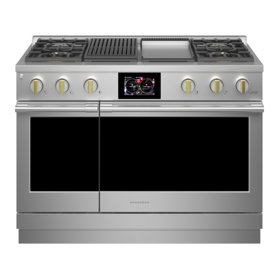
Introduction *Monogram introduces the new GE Monogram Professional Range and Rangetops. Their superior style and performance parallel commercial units. Available in 48-, 36-, and 30-inch Ranges and 48- and 36-inch Rangetop models -- these units feature electronic dial controls that combine the precision of modern digital technology with the simplicity of traditional mechanical controls. -
Page 6: Nomenclature - Range
Nomenclature - Range Model Number Z D P 4 8 6 N D P S S Monogram Product Product Color Monogram Pro Range SS = Stainless Steel Width Model Year Designator 48 = 48-in. Range Additional Cooking Surface 36 = 36-in. Range D = Griddle 30 = 30-in. -
Page 7: Nomenclature - Rangetop
Nomenclature - Rangetop Model Number Z G U 4 8 6 N D P S S Monogram Product Product Color Monogram Gas Rangetop SS = Stainless Steel Width Model Year Designator 48 = 48-in. Range Additional Cooking Surface 36 = 36-in. Range D = Griddle R = Grill Number of Surface Burners... -
Page 8: Control Features - Rangetop
Control Features - Rangetop Design information (Not all features are on all models. Appearance may Grill and Griddle Covers vary.) Bamboo Cutting Board ZGU486NR, ZGU486LR–6 burners and grill ZGU486ND, ZGU486LD–6 burners and griddle Number Feature Feature Index Page Bamboo Cutting Board Bamboo Cutting Board Grill and Griddle Covers Grill and Griddle Covers... - Page 9 Cooktop Controls After the burner ignites, turn the knob to adjust the fl ame size. Electronic Ignition and Automatic Reignition To turn a burner off, turn the knob clockwise, as far The range is equipped with electronic ignition which as it will go, to the OFF position. eliminates the need for a standing pilot light.
- Page 10 Using the IR Grill To heat the griddle, push in the control knob and turn to the desired Temperature setting. The light on Remove the cover before lighting the burner. The the bezel will glow to indicate the thermostat control cover must be removed when using the IR grill.
-
Page 11: Control Features - Range
Appearance may Grill and Griddle Covers vary.) Bamboo Cutting Board Toekick ZDP486NR, ZDP486LR–6 burners and grill ZDP486ND, ZDP486LD–6 burners and griddle ZDP484NG, ZDP484LG 4 burners, grill and griddle Double oven model shown includes a small oven. Number Feature Bamboo Cutting Board... - Page 12 Oven Control and Timer 1. Oven Mode Selector – Turn outer ring to select: PROOF – Maintains a warm environment useful for rising yeast-leavened products. BAKE – Select for traditional baking. CONV BAKE – Use for convection baking. CONV ROAST – Use for convection roasting. CONV BROIL –...
- Page 13 How to Set the Oven for Baking Turn the Oven Mode Selector to BAKE. Using the Temperature knob, set the desired temperature, in 25°F increments, from 175°F to 550°F. Oven Mode Selector (Outer) Oven Temperature Knob (Inner) The oven will now begin to preheat. The temperature display will begin at 100ºF and remain there until the oven exceeds that temperature.
- Page 14 How to Set the Oven for Broiling and Convection Broiling Turn the Oven Mode Selector to BROIL or CONV BROIL. Turn the Oven Temperature Knob to LO BROIL or HI BROIL. LO or HI will appear in the display. Oven Mode Selector (Outer) Oven Temperature Knob (Inner)
- Page 15 Introduction to Convection Cooking The Monogram reverse-air convection system consists of two dedicated heating elements wrapped around the convection fan. After preheating to the set temperature, all heat in CONV BAKE mode comes from these two dedicated elements. The convection fan periodically pauses, then changes direction to best distribute hot air throughout the oven.
- Page 16 How to Set the Oven for Proofi ng How to Set the Oven for Cleaning The proofi ng feature maintains a warm environment Caution: See owner's Manual for Self-cleaning which is useful for rising yeast-leavened dough. safety precautions. Turn the Oven Mode Selector to PROOF.
- Page 17 How to Set the Oven Timer Oven Thermostat Adjustment Note: You may fi nd that your new oven cooks differently than the one it replaced. Use your new oven for a • The timer is independent of all the other few weeks to become more familiar with it.
- Page 18 Sabbath Mode* To set the Sabbath mode: The Sabbath mode is designed for use on the Jewish Sabbath and other Jewish holidays. It can be used for baking only. It cannot be used for any other cooking mode. When the Sabbath feature is set, the oven light and all audible beeps will be disabled.
-
Page 19: Installation
Installation Installation information is for reference only. See the Range Electric Supply Installation Instructions shipped with the product for These ranges must be supplied with 208/240 volt, complete details and before attempting to install the 60 Hz., and connected to an individual, properly range or rangetop. - Page 20 Leveling the Range 3. Use the supplied wrench to turn the front leveling legs. Turn clockwise to raise the range WARNING: above the wheels. Turn counterclockwise to lower the legs. • All ranges can tip. Injury could result. Install the supplied Anti-Tip Bracket.
- Page 21 3. Secure the top and bottom sections by Range Anti-Tip Device tightening the 2 screws on each end. WARNING: All ranges can tip. BURNS or other SERIOUS INJURIES can result. INSTALL and CHECK Top of the ANTI-TIP bracket following these instructions. Toekick To reduce the risk of tipping the range, the range must be secured by a properly installed anti-tip...
-
Page 22: Gas Conversion Range And Rangetop
Attach the Anti-Tip Brace onto the bottom of the Gas Conversion Range and Rangetop range in the recessed area. Install 2 hex screws (provided) through the brace and into the range. WARNING: Note: This Anti-Tip device may be installed on the This conversion must opposite side of the range. - Page 23 CONVERT THE REGULATOR CHANGE BURNER ORIFICES (cont.) IMPORTANT: Find your model number below. Read Disconnect all electrical power at the main circuit each orifice label to identify and install them in the breaker or fuse box. exact locations shown. A. Remove the rear vent Range Regulator trim (on ranges only) ZDP304 SIMMER ORIFICES...
- Page 24 CHANGE GRILL ORIFICE CHANGE GRIDDLE ORIFICE (if present) (if present) Locate the 3/4" long Griddle orifice. — — Select for your gas type. LP .047, NAT .076 Locate the 1–1/2" long Grill orifice. — — Select for your gas type. LP .047, NAT .067 A.
-
Page 25: Oven Operational Notes
Oven Operational Notes ADJUST BURNER FLAMES Certain modes, when selected, will automatically Normally, burners do not need further adjustment. enter into a preheat. The temperature knob is used Make adjustments only when necessary. to set the desired temperature, in 25°F increments, A. - Page 26 • The convection fan will cycle on and off while cooking to best distribute hot air in the oven. The convection fan shuts off when the oven door is opened. • Different broil elements are used in each broil mode. There are 2 different broil modes, each providing a HI and a LO setting.
-
Page 27: Component Locator Views
Component Locator Views Front of Range (48-in. range shown) Rangetop Task Light Switch Control Panel Broil Element Broil Element Lights Lights Lights Convection Fan Convection Fan Oven Door Gasket Oven Door Gasket Oven Door Oven Door (Continued next page) – 27 –... - Page 28 Rear of Range (48-in. range shown) Level Leg Extension Rod Level Leg Extension Rod Regulator Shutoff Valve Sail Switch Sail Switch Cooling Fan Cooling Fan Broil Element Broil Element Oven TCO Oven TCO Convection Fan Convection Fan Convection Element Convection Element Terminal Block Gas Inlet Pipe (Continued next page)
- Page 29 Rangetop ZGU484NG IR (Infrared) Grill Griddle Griddle Control Knob IR (Infrared) Grill Control LED Task Burner Control Knob with Lighted Bezel Knob with Lighted Bezel Lighting with Lighted Bezel Control (1 of 4) Rangetop ZGU484NG (burner pans, top heat barriers, grill, and griddle removed) Grill Burner Igniter Burner Burner...
-
Page 30: Control Panel
Surface Components WARNING: Sharp edges may be exposed when 3. Remove the 2 Phillips-head screws within each servicing. Use caution to avoid injury. Wear Kevlar bezel that attach the bezel to the manifold gloves or equivalent protection. brackets. Control Panel It is necessary to remove the control panel from the range or rangetop chassis and place it in the service position to access certain components. -
Page 31: Grill Assembly
6. On rangetops, remove the two 1/4-in. hex-head Grill Assembly screws and the Phillips-head screw (on each side), from the back of the control panel fl ange. Note: The following describes the procedure to remove the grill assembly. To remove the grill: Lift off the grill grate and grill frame. - Page 32 6. Remove the two 1/4-in. hex-head screws from 8. Remove the grill burner igniter. (See Grill Burner the front and the two 1/4-in. hex-head screws Igniter from the rear of the grill burner. 9. Place the control panel in the service position. (See Control Panel 10.
-
Page 33: Grill Burner Igniter
Grill Burner Igniter Grill Safety Valve Note: The following describes the procedure to Note: The following describes the procedure to remove the grill burner igniter. The grill igniter remove the grill safety valve. The grill safety valve has a resistance value of 45 to 400 Ω at room has a resistance value of 1 Ω... -
Page 34: Grill Control
4. Using a ratchet wrench, remove the 1/4-in. Grill Control hex-head screw that attaches the control to the manifold. The grill control is attached to the manifold bracket. A switch bracket is attached to the control and secures 2 switches. The front switch controls the igniter and the rear switch controls the LED indicator. -
Page 35: Griddle Assembly
Caution: The griddle is heavy. Use care when lifting Griddle Assembly and rotating the griddle to prevent damage to the capillary. Note: The following describes the procedure to remove the griddle assembly. 4. Lift and rotate the griddle and remove the 2 Phillips-head screws and the retainer from the To remove the griddle assembly: bottom of the griddle. - Page 36 Note: In the following step, ensure that the spring 13. Remove the 2 Phillips-head screws from the clip is captured and retained inside the griddle front and the 2 Phillips-head screws from the burner box. rear of the griddle burner box. 6.
-
Page 37: Griddle Burner Igniter
Griddle Burner Igniter Griddle Control The griddle burner igniter is attached to the right The control utilizes a capillary that senses griddle side of the griddle burner with two 1/4-in. hex- temperature and a switch that operates the LED head screws. It is necessary to remove the griddle indicator light. -
Page 38: Grill And Griddle Ignition Systems
5. Slide the switch off the switch plate. Grill and Griddle Ignition Systems The grill and griddle burners are ignited by a glow- LED Switch bar ignition system. The igniter is a Norton style rectangular glow-bar. The grill and griddle ignition circuits consist of the control, an igniter, a hi limit switch (griddle only), and a safety valve. -
Page 39: Glow-Bar Igniter
Surface Burner Base Glow-bar Igniter Note: The following describes the procedure to WARNING: The range and rangetop use rect- remove a single burner base. The procedure to angular Norton glow-bar igniters. They are NOT remove the remaining burner bases is identical. INTERCHANGEABLE with cylindrical Carborundum glow-bar igniters. -
Page 40: Surface Burner Igniter
Surface Burner Igniter Surface Burner Pan Note: The following describes the procedure to Ranges remove a single igniter. The procedure to remove the The following procedure describes the removal of remaining igniters is identical. the left-side surface burner pan on range models. To remove the igniter: The procedure to remove the right-side burner pan is similar. -
Page 41: Surface Burner
7. Lift and tilt the right side of the burner pan, then Surface Burner carefully slide it out from under the left-side panel. Note: The following describes the procedure to remove a single burner. The procedure to remove the remaining burners is identical. To remove the burner: Remove the burner base. -
Page 42: Surface Burner Valve And Switch
5. Slide down and remove the wiring retainer clip Surface Burner Valve and Switch from the frame. Each surface burner valve utilizes a switch. When a 6. Using a ratchet wrench, remove the 1/4-in. burner knob is turned to the ON position, the valve hex-head screw that attaches the valve to the switch closes and activates the spark module and manifold. -
Page 43: Spark Module
5. Remove the 2 Phillips-head screws that attach Spark Module the module to the burner box. The spark module is located under the left-side 6. Remove the Phillips-head screw that secures the surface burner pan. module wire harness. To remove the spark module: 7. -
Page 44: Transformer
6. Maneuver the transformer to the right, then Transformer rotate the bracket forward to the horizontal position. The transformer is located under the left-side surface burner pan. The transformer windings have 7. Disconnect the (secondary) wiring connector an approximate resistance value between: from the transformer harness that is retained in Brown to brown (120 VAC primary) - 33 Ω... -
Page 45: Led Lights And Power Supply
On range models, the LED power supply is located LED Lights and Power Supply above the surface burner manifold on the left side of the control area. It is accessible by placing the The LED lights (task lighting) are located inside the control panel in the service position. -
Page 46: Indicator Light Assembly
Task Light Switch Indicator Light Assembly The task light switch is attached to the left side of Each surface unit (surface burner, grill, and griddle), the control panel with a 3/4-in. hex nut. utilizes an indicator light consisting of a circuit board with an attached Light Emitting Diode (LED). -
Page 47: Back Panel
Range Components Back Panel Side Access Panel The back panel is attached with seventeen 1/4-in. To remove the side access panel: hex head screws. It is necessary to remove the Remove the range from the installation. (See range from the installation to access the screws. Installation (See Installation... -
Page 48: Cooling Fan
Note: The side panel is held to the front side of the Cooling Fan range with 3 keyslots inside the panel that engage 3 plastic pins on the range. The cooling fan is attached on the back of the oven with two 1/4-in. -
Page 49: Lock Assembly
Sail Switch Lock Assembly The sail switch is located at the top rear of the The motorized door lock assembly is located above range, above the cooling fan. This switch monitors the oven. The assembly consists of a lock motor the presence of the airstream from the cooling fan. - Page 50 If the lock motor fails during a self-clean cycle, Unlock Lock Switch Switch there is suffi cient space between the oven door and control panel to remove the 2 Phillips-head screws holding the lock motor assembly. Carefully opening the door will pull the lock motor assembly out far Door enough to service.
-
Page 51: Door Assembly
Oven Components To replace the outer door assembly: Door Assembly Separate the door assemblies. (See To separate The oven door can be separated into 2 assemblies. the door assemblies, this section The outer assembly consists of the outer panel and a replaceable door handle. - Page 52 To replace the inner door assembly: Assembly Notes Remove the outer door assembly. (See When assembling, make sure the hinges are parallel Door to each other and perpendicular to the door liner. If Assembly not, the hinge may bind on the receiving channel of Remove the 4 T-20 Torx screws (2 on each side) the door.
- Page 53 Oven Doors (exploded view) Companion Oven Door Main Oven Door – 53 –...
-
Page 54: Oven Racks
To install a rack: Oven Racks 1. Place the rear rack locks over and onto the WARNING: To avoid possible burns, remove or install rack supports. (Five rack positions are available, the racks before turning on the oven. including the top position.) To remove a rack: 1. - Page 55 2. Fully extend the rack on a table or countertop. Repeat for the right slide mechanism of the rack. Newspaper may be placed underneath the rack for easy clean up. Right side Rack right-side-up Open and close the rack several times to If there is debris in the slide tracks, wipe it distribute the lubricant.
-
Page 56: Broil Elements
Oven Temperature Sensor Broil Elements The oven temperature sensor has a resistance of: The broil cycle is closed door only. The display will scroll “CLOSE door” if the door is left open in the broil Ω at room temperature • 1091 cycle. -
Page 57: Convection Bake Element
4. Remove the two 1/4-in. hex-head screws that Convection Bake Element attach the element bracket to the oven liner. • The convection bake element is composed of an inner and an outer element. It is replaced as one unit. • The main oven inside element is rated at 900 watts, has an approximate resistance value of 62 Ω, and draws approximately 3.4 amps. -
Page 58: Convection Fan Assembly
3. Remove the three 1/4-in. hex-head screws that Convection Fan Assembly hold the convection bake element to the back wall of the oven cavity. The convection fan assembly is located on the back wall of the oven cavity and consists of the fan guard, blade, insulation, and motor. - Page 59 Convection Airfl ow Caution: To avoid scratching the oven fl oor, cover the fl oor with protective surface. 4. Carefully pull the fan assembly into the oven cavity and disconnect the fan motor wire harness. Disconnect The convection fan motor has approximate resistance values between the following wires: White to yellow/blue (CW) - 92 Ω...
-
Page 60: Oven Control Logic Board
Oven Control Logic Board Oven Relay Board The oven control logic board consists of several The oven relay board is located below the oven boards and a frame. The logic board controls oven cavity and is accessed by removing a bottom panel operation through user input and feedback from the and lowering the board to the fl... -
Page 61: Bake Element
4. Remove the lower access panel. Bake Element • Both main and companion ovens utilize true Remove screws Lower hidden bake elements. Access Panel • The bake element is composed of 2 elements and is replaced as one unit. • The main oven bake element number 1 is rated at 1200 watts, has an approximate resistance value of 46.6 Ω, and draws approximately 4.6... - Page 62 7. Remove the 1/4-in. hex-head screw on the left 11. Note the position of the wiring harness through end of the cover plate. the opening in the bottom of the shelf and the surrounding gasket. Gasket and Opening 8. Slide the cover plate to the left to disengage the tab, then remove the cover plate.
-
Page 63: Meat Probe Receptacle And Harness
12. Slide the hidden bake element out from the Meat Probe Receptacle and Harness range. Each oven is equipped with a meat probe receptacle and harness. The probe outlet is located near the Main Oven Bake Element top right front corner of the oven cavity on 30- and 36-in models, and on the right side of the main oven and the left side of the companion oven on 48-in models. - Page 64 To remove the meat probe receptacle harness: 6. Carefully pull the probe wire harness, and part of the retrieval wire through the light housing Remove the range from the installation. opening. Remove the back panel. (See Back Panel Disconnect the meat probe outlet wire harness. Disconnect 7.
-
Page 65: Oven Light Assemblies
5. Remove the racks, rack support, and light cover. Oven Light Assemblies (See , this section.) Oven Light Bulbs Each main oven is equipped with two halogen light 6. Remove the two 1/4-in. hex-head screws that assemblies located on the side walls of the oven. attach the light housing to the oven liner. - Page 66 Procedure B: 3. Remove the glass light cover by pulling its back edge out and rolling it toward you. Do not Remove the racks, rack support, and light cover. remove any screws. (See , this section.) Oven Light Bulbs Remove the two 1/4-in. hex-head screws that attach the light housing to the oven liner.
-
Page 67: Electronic Oven Control
Electronic Oven Control Overview The Electronic Oven Control system consists of the logic board, power supply board, relay board, oven controls, oven sensor, and door lock assembly. Caution: Certain components are electrically HOT when voltage is connected to range. • Bake, broil, and convection units can be on at the same time. -
Page 68: Control Board Connector Locator
Control Board Connector Locator Temperature Display Board Sensor Connections Meat Probe Connections Temperature Display Board *LINbus *LINbus Logic Board Dual Encoder Board Dual Encoder Board Dual Encoder Board *LINbus: (Local Interconnect Network) : A communication network comprised of a LIN master and one or more LIN slaves. - Page 69 Oven Relay Board Daughter Relay Module Relay Power Supply Module Note: The main oven relay board consists of a relay power supply module and a daughter relay module, available only as an assembly. Companion oven relay boards are similar, but will not have a power supply. Relay Power Supply Door Lock,, Broil Element 2, Bake Element 2, Convection Element 2, L1, Convection Motor CW, Convection Motor CCW...
- Page 70 Oven Relay Board Wiring Diagrams WS RN RY RW YR R W B Y S MAIN OVEN RELAY BOARD S O N G Y R (AS VIEWED FROM FRONT OF RANGE) WS RN RY RW YR R W B Y S SMALL OVEN RELAY BOARD S O N...
-
Page 71: Diagnostics And Service Information
Diagnostics and Service Information Factory Test Mode The Factory Test mode can be accessed within the fi rst 2 minutes of power up, before any other selections are made. Press and hold the PUSH TO SELECT knob for approximately 3 seconds within the fi rst 2 minutes. The display will show “Prod”. - Page 72 Note: The table below shows the component sequence when Factory Test mode starts. This is a End-of-Line test and cannot be paused to test components. Step Sequence Action 0.0 seconds Wait 2.0 seconds Turn on Bake 1 Element 4.0 seconds Turn off Bake 1 Element and wait 5 seconds Turn on Bake 2 Element...
- Page 73 After completing the component sequence, pressing 6th press displays all green LED segments the Timer button scrolls through these available displays. 1st press displays ROM revision 7th press displays EEPROM programming 2nd press displays EEPROM checksum 8th press displays F-Codes 3rd press displays Probe temperature Note: 7 fault codes are stored in memory 4th press displays oven temperature...
- Page 74 Failure Codes The last 7 Failure (F) codes are stored in the nonvolatile memory, accessed through the factory test mode. All Failure (F) codes are suppressed from the display, except F2 and F9. To access the last 7 F-codes, follow these steps: 1.
- Page 75 Miswire Detection A miswire error is detected if any of the power supply lines (L1, L2 or N) are wired incorrectly or not present. If detected, the control will beep continuously and scroll “Bad LinE” across available displays (main and companion oven, if applicable).
-
Page 76: Oven Sensor, Sail, And Door Switch Test
Oven Sensor, Sail, and Door Switch Test Note: See for door switch function explanation. Lock Assembly Remove power from oven. The resistance measurements are made on the main logic board at connector J5 and J6, and the oven relay board at connectors J16 and J17. If abnormal reading is observed, wiggle leads at disconnect block. -
Page 77: Schematics And Wiring Diagrams
Schematics and Wiring Diagrams WARNING: Disconnect electrical power before servicing. Caution: Label all wires prior to disconnection. Wiring errors can cause improper and dangerous operation. Verify operation after servicing. Rangetop Schematic (Continued Next Page) – 77 –... - Page 78 Rangetop Wiring Diagram – 78 –...
-
Page 79: Surface Component Circuits
Surface Component Circuits Surface Burner (4 burner model shown) 120 VAC INPUT 33 Ω TRANSFORMER 188 Ω 240 VAC OUTPUT VALVE SWITCH VALVE SWITCH SPARK MODULE VALVE SWITCH VALVE SWITCH LED Board POWER SUPPLY FRONT PANEL BOARD BOARD BOARD BOARD BOARD BOARD BOARD... - Page 80 Grill 120 VAC INPUT 33 Ω TRANSFORMER SAFETY 188 Ω VALVE 240 VAC OUTPUT Ω IGNITER GLOW BAR 3.40 - 3.60 amps GRILL VALVE 45 - 400 Ω SWITCHES Griddle 120 VAC INPUT 33 Ω TRANSFORMER 188 Ω 240 VAC OUTPUT SAFETY VALVE Ω...
-
Page 81: Oven Component Circuits
Oven Component Circuits Preheat Circuit N.C. BAKE 140 C ELEMENT 1 LIMIT 284 F N.O. 47Ω N.C. BROIL ELEMENT 1 N.O. 19Ω N.C. N.O. CONVECTION ELEMENT 2 J7-4 62Ω BAKE ELEMENT 2 J7-3 56Ω BROIL ELEMENT 2 J7-2 55Ω J7-12 N.C. - Page 82 Bake Circuit N.C. BAKE ELEMENT 1 N.O. 140 C LIMIT 284 F 47Ω N.C. BROIL ELEMENT 1 2.2 Ω N.O. 19Ω BAKE ELEMENT 2 56Ω BROIL ELEMENT 2 J7-2 55Ω J5-2 J7-7 LOW SPEED COOLING Closed above 200 F OVEN LAMP J5-5 CYCLING...
- Page 83 Convection Circuit N.C. N.C. CONVECTION 140 C LIMIT ELEMENT 1 284 F N.O. N.O. 47Ω N.C. N.O. N.C. N.O. CONVECTION ELEMENT 2 J7-4 62Ω J7-12 N.C. 92Ω J7-7 J7-10 N.O. 77Ω CONVECTION J5-1 J5-2 LOW SPEED 20Ω COOLING Closed above 200 F J5-5 OVEN LAMP...
-
Page 84: Optional Accessories
Optional Accessories Optional Backsplashback Kits Optional Black Knob Kits Two optional backsplash kits are available for Optional black knob kits are available for ranges and ranges and rangetops: rangetops. • 12-inch tall stainless steel backsplash Range Models Part Number • 36-inch tall backsplash equipped with a shelf ZDP304N/LPSS WB03K10268... -
Page 85: Warranty-Rangetop
Warranty-Rangetop YOUR MONOGRAM RANGETOP WARRANTY Staple sales slip or cancelled check here. Proof of original purchase date is needed to obtain service under warranty. Please have serial number and model number available when calling for service. WHAT IS LIMITED TWO-YEAR WARRANTY This warranty is extended to the original purchaser and any succeeding owner for COVERED... -
Page 86: Warranty-Range
Warranty-Range YOUR MONOGRAM RANGE WARRANTY Staple sales slip or cancelled check here. Proof of original purchase date is needed to obtain service under warranty. Please have serial number and model number available when calling for service. WHAT IS LIMITED TWO-YEAR WARRANTY This warranty is extended to the original purchaser and any succeeding owner for COVERED...
Need help?
Do you have a question about the Monogram ZDP486ND and is the answer not in the manual?
Questions and answers