Mitsubishi Electric PEA-RP200GA Service Manual
Split-type, heat pump air conditioners
Hide thumbs
Also See for PEA-RP200GA:
- Technical data manual (126 pages) ,
- Technical data book (88 pages)
Advertisement
Table of Contents
- 1 Table of Contents
- 2 Service Manual
- 3 Model Names
- 4 Types of Connected Outdoor Units
- 5 Safety Precaution
- 6 Part Names and Functions
- 7 Specifications
- 8 Data
- 9 Indoor Units
- 10 Outlines and Dimensions
- 11 Wiring Diagram
- 12 Refrigerant System Diagram
- 13 Troubleshooting
- 14 Service Data (Parts Name)
- Download this manual
SPLIT-TYPE, HEAT PUMP
AIR CONDITIONERS
SERVICE MANUAL
[Model names]
PEA-RP200GA
PEA-RP250GA
PEA-RP400GA
PEA-RP500GA
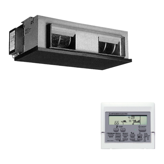
Indoor unit
CONTENTS
2. SAFETY PRECAUTION ···································3
3. PART NAMES AND FUNCTIONS····················8
4. SPECIFICATIONS ··········································10
5. DATA ·······························································11
6. OUTLINES AND DIMENSIONS ·····················13
7. WIRING DIAGRAM ·········································16
8. REFRIGERANT SYSTEM DIAGRAM ············18
9. TROUBLESHOOTING ····································19
10. SERVICE DATA (PARTS NAME) ···················30
Remote controller
2007
• This manual describes only
service data of the indoor
units.
Advertisement
Table of Contents
Troubleshooting


Need help?
Do you have a question about the PEA-RP200GA and is the answer not in the manual?
Questions and answers