
Related Manuals for Mitsubishi Electric PEA-RP200 GAQ


Summary of Contents for Mitsubishi Electric PEA-RP200 GAQ
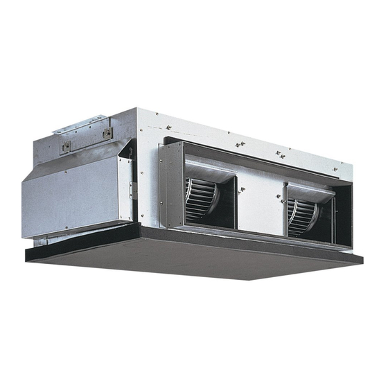
- Page 1 Air-Conditioners INDOOR UNIT PEA-RP200, 250, 400, 500 GAQ FOR INSTALLER INSTALLATION MANUAL For safe and correct use, please read this installation manual thoroughly before installing the air-conditioner unit.
- Page 2 [Fig. 2.0.1] 1 Pipe cover (For field piping connection) [Fig. 3.2.1] * In case of PEA-200, 250 * In case of PEA-400, 500 1800 2400 Model PEA-200 1860 1260 PEA-250 2060 1460 1 When connecting air inlet 2 When installing the suspension fixtures prior to installation of the indoor unit without inlet duct 3 When hanging the indoor unit directly without inlet duct A Service space...
- Page 3 [Fig. 5.1.1] [Fig. 5.1.2] A Nut B Washer A Unit body B Lifting machine [Fig. 5.1.3] [Fig. 5.2.1] A Be sure to attach a U-shaped washer (4 washers in total). A Level check [Fig. 6.2.1] * In case of PEA-200, 250 * In case of PEA-400, 500 Model PEA-200, 250...
- Page 4 [Fig.7.2.1] A Insulator B Drain pipe R1 C Drain pan > = 70 mm 2 × F > = > = 70 mm > = 35 mm G Downward slope 20 mm/m or more H Drain trap I The drain pipe should extend below this level. J Open drain [Fig.8.0.1] A Air inlet...
- Page 5 [Fig.9.0.1] * In case of PEA-200, 250 PUHZ-200, 250 PEA-200, 250 L1 L2 L3 N S1 S2 S3 S1 S2 S3 L1 L2 L3 N * In case of PEA-400, 500 (No.1 Outdoor) PUHZ-200, 250 PEA-400, 500 (TB4-1) (TB4-2) L1 L2 L3 N S1 S2 S3 S1 S2 S3 S1 S2 S3...
- Page 6 10.1 [Fig.10.1.1] * In case of PEA-200, 250 * In case of PEA-400, 500 A Outdoor unit B Indoor unit No.1 No.2 No.1 No.2 No.1 No.2 C Main remote controller D Subordinate remote controller E Standard (Refrigerant address = 00) F Refrigerant address = 01 G Refrigerant address = 02 H Refrigerant address = 03...
-
Page 7: Table Of Contents
Contents 1. Safety precautions ..................7 9. Electrical wiring ..................11 1.1. Before installation ..............8 10. System control ..................12 1.2. Before installation (relocation) ........... 8 10.1 Grouping by using LCD remote controller ....... 12 1.3. Before electrical work ..............8 10.2 Examples of refrigerant system address setting ..... -
Page 8: Before Installation
1.1. Before installation 1.3. Before electrical work Caution: Caution: • Do not install the unit where combustible gas may leak. • Ground the unit. - If the gas leaks and accumulates around the unit, an explosion may result. - Do not connect the ground wire to gas or water pipes, lightning rods, or •... -
Page 9: Combining Indoor Units With Outdoor Units
Service space Suspension bolt pitch [Fig. 3.2.1] (P.2) [Fig. 3.2.2] (P.2) D Suspension bolt pitch E Top of the unit 1 When connecting air inlet 2 When installing the suspension fixtures prior to installation of the indoor unit with- F Suspension bolt holes out inlet duct PEA-200, 250 : 4-ø12 holes PEA-400, 500 : 4-ø15 holes... -
Page 10: Refrigerant Pipe And Drain Pipe Specifications
6. Refrigerant pipe and drain pipe specifications To avoid dew drops, provide sufficient antisweating and insulating work to the re- 6.1. Refrigerant pipe and drain pipe specifi- frigerant and drain pipes. cations When using commercially available refrigerant pipes, be sure to wind commer- cially available insulating material (with a heat-resisting temperature of more than 100 °C and thickness given below) onto both liquid and gas pipes. -
Page 11: Duct Work
1. Ensure that a drain trap is installed. If this is neglected, condensation may from waving. Never provide any air vent pipe. Otherwise drain may be ejected. occur inside the indoor unit leading to water leakage/equipment breakdown, 4. Use a hard vinyl chloride pipe VP-25 (with an external diameter of 32 mm) for etc. -
Page 12: System Control
[Wiring example] (For metal piping) Local switch Earth leakage Indoor and outdoor Remote controller Power cable *4 Earth cable Switch capacity Overcurrent Circuit breaker breaker *1, *2 connection wiring *5 wiring <A> protector *3 <A> 15 A 30 mA 0.1s. 0.3 - 1.25 mm 1.5 mm or more... -
Page 13: Lcd Remote Controller
11. LCD remote controller (option) <B> For direct installation on the wall 11.1. Installing procedures H Wood screw (1) Select an installing position for the remote controller (switch box). Caution: Be sure to observe the following precautions. Do not over-tighten the screws to possible deformed or broken lower case. [Fig.11.1.1] (P.6) Note: A Remote controller profile... - Page 14 [Function selection flowchart] [1] Stop the air conditioner to start remote controller function selection mode. → → → → → [2] Select from item1. → → → → → [3] Select from item2. → → → → → [4] Make the setting. (Details are specified in item3) →...
- Page 15 (2) Unit Function Selection Set the functions of each indoor unit from the remote controller, as required. The functions of each indoor unit can be selected only from the remote controller. Set the functions by selecting the necessary items from Table 1 and Table 2. (Default settings are also shown below) Table 1.
- Page 16 4 Set the indoor unit address No. When the C [ CLOCK ( ) and ( )] buttons are pressed, the unit address Press the D [ ON/OFF] button. The unit address No. display “– –” flashes. No. changes in 00 → 01 → 02 → 03 → 04 → AL order. Set it to the unit address No.
-
Page 17: Test Run
12. Test run 5 Press the [ ON/OFF] button to reset the test run in progress 12.1. Before test run • The test run will be automatically shut down after two hours in response to the The test run can be carried out either from the outdoor unit or the indoor unit. AUTO STOP setting of two hours on the timer. -
Page 18: Self-Check
Press the remote controller’s “CHECK” button twice consecutively to be able to run a self-check. See the chart below for content of error code displays. Nonconformity Content Nonconformity Content Nonconformity Content Return air temperature sensor error Pipe temperature error/Outdoor unit error E6 ~ EF Signal error between indoor and outdoor Pipe (TH2) sensor error... -
Page 19: Troubleshooting
3 Remote controller check result When remote controller is normal When remote controller is faulty (Error display 1) “NG” flashes → Remote controller send/receive circuit abnormal Since there is no problem at the remote controller, check for other causes. Remote controller switching is necessary. When the problem is other than the checked remote controller (Error display 3) “ERC”... -
Page 20: The Following Occurrences Are Not Problems Or Errors
13.2. The following occurrences are not problems or errors Problem Remote controller display Cause During thermostat OFF mode, low speed air operation will take place. The fan setting changes during heating. Ordinary display During thermostat ON mode, low speed air will switch automatically to set notch (fan (PEA-200, 250) speed) on the basis of time or piping temperature. - Page 21 Please be sure to put the contact address/telephone number on this manual before handing it to the customer. HEAD OFFICE: TOKYO BLDG., 2-7-3, MARUNOUCHI, CHIYODA-KU, TOKYO 100-8310, JAPAN Authorized representative in EU: MITSUBISHI ELECTRIC EUROPE B.V. HARMAN HOUSE, 1 GEORGE STREET, UXBRIDGE, MIDDLESEX UB8 1QQ, U.K. KB79U753H01...
Need help?
Do you have a question about the PEA-RP200 GAQ and is the answer not in the manual?
Questions and answers