Table of Contents
Advertisement
Advertisement
Table of Contents
Troubleshooting

Related Manuals for Planet FNSW-2400PS


Summary of Contents for Planet FNSW-2400PS
- Page 1 User's Manual FNSW-2400PS 24-Port 10/100Mbps POE Web Smart Ethernet Switch - 1 -...
-
Page 2: Fcc Warning
Trademarks Copyright © PLANET Technology Corp. 2011. Contents subject to revision without prior notice. PLANET is a registered trademark of PLANET Technology Corp. All other trademarks belong to their respective owners. Disclaimer PLANET Technology does not warrant that the hardware will work properly in all environments and applications, and makes no warranty and representation, either implied or expressed, with respect to the quality, performance, merchantability, or fitness for a particular purpose. -
Page 3: Table Of Contents
User’s Manual of FNSW-2400PS TABLE OF CONTENTS 1. INTRODUCTION ................6 1.1 C ..............................6 HECKLIST 1.2 A ........................... 6 BOUT THE WITCH 1.3 F ..............................7 EATURES 1.4 S ............................8 PECIFICATION 2. HARDWARE DESCRIPTION ............10 2.1 F ............................ - Page 4 User’s Manual of FNSW-2400PS 4.5 Q ............................37 ETTING 4.5.1 Priority Mode ........................... 37 4.5.2 Class of Service ..........................38 4.6 S ..............................41 ECURITY 4.6.1 MAC Address Binding........................42 4.6.2 TCP / UDP Scan ..........................43 4.6.3 TCP / UDP Filter ..........................43 4.6.4 IP Address Filter ..........................
-
Page 5: Troubleshooting
User’s Manual of FNSW-2400PS 8. TROUBLESHOOTING ............... 67 APPENDIX A NETWORKING CONNECTION.......... 68 A.1 S ‘ RJ-45 P ......................68 WITCH SSIGNMENTS A.2 RJ-45 ......................... 68 CABLE PIN ASSIGNMENT A.3 DATA OUT P RJ-45 P ..............69 NJECTOR SSIGNMENTS - 5 -... -
Page 6: Introduction
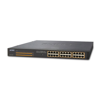
1.2 About the Switch The FNSW-2400PS provides 24 10/100Mbps POE Fast Ethernet ports, the Web Smart PoE Switch supports MDI / MDI-X convertible on 24 10/100Mbps ports and also provides PoE inject function on port#1 to port#24 which is able to drive at least 8 IEEE 802.3af 15.4Watts compliant powered devices. -
Page 7: Features
User’s Manual of FNSW-2400PS 1.3 Features Physical Port 24-Port 10/100Mbps Fast Ethernet ports with PoE Injector Reset button for system management Complies with IEEE 802.3af Power over Ethernet Mid-Span PSE Up to 24 IEEE 802.3af devices powered Supports PoE Power up to 15.4 Watts for each 802.3af PoE port... -
Page 8: Specification
User’s Manual of FNSW-2400PS Management idle time security Management Remote Web interface for Switch management and setup Supports SNMP v1 Supports DHCP Option82 and DHCP Relay Firmware upgrade through Web interface Configuration upload / download through Web interface Reset button for system reboot or reset to factory default 1.4 Specification... - Page 9 User’s Manual of FNSW-2400PS RSTP, IEEE 802.1w (Rapid Spanning Tree Protocol) Support 2 groups of 4-Port 10/ 100Base-TX trunk support Port Trunking Up to 800Mbps bandwidth per trunk (Full-Duplex) Port mirroring allows monitoring of the traffic across any port in real time Port Mirroring Allow to assign low / high priority on each port.
-
Page 10: Hardware Description
This section describes the hardware features of FNSW-2400PS. For easier management and control of the FNSW-2400PS, familiarize yourself with its display indicators, and ports. Front panel illustrations in this chapter display the unit LED indicators. Before connecting any network device to the FNSW-2400PS, read this chapter carefully. -
Page 11: Hardware Installation
User’s Manual of FNSW-2400PS Power Notice: 1. The device is a power-required device, it means, it will not work till it is powered. If your networks should active all the time, please consider using UPS (Uninterrupted Power Supply) for your device. It will prevent you from network data loss or network downtime. -
Page 12: Rack Mounting
User’s Manual of FNSW-2400PS 2.3.2 Rack Mounting To install the POE Web Smart Ethernet Switch in a 19-inch standard rack, follow the instructions described below. Step 1: Place your POE Web Smart Ethernet Switch on a hard flat surface, with the front panel positioned towards your front side. - Page 13 User’s Manual of FNSW-2400PS Figure 2-4 Mounting the POE Web Smart Ethernet Switch in a Rack Step 6: Precede with the steps 4 and steps 5 of section 2.3.1 Desktop Installation to connect the network cabling and supply power to your POE Web Smart Ethernet Switch.
-
Page 14: Switch Management
User can manage the POE Web Smart Ethernet Switch by Web Management via a network connection. 3.2.1 Web Management The PLANET FNSW-2400PS provide a built-in browser interface. You can manage the Switch remotely by having a re- mote host with Web browser, such as Microsoft Internet Explorer, Netscape Navigator or Mozilla Firefox. -
Page 15: Logging On To The Fnsw-2400Ps
User’s Manual of FNSW-2400PS 3.3 Logging on to the FNSW-2400PS When you log on to the POE Web Smart Ethernet Switch Web interface for the first time, a sign-on string appears and you are prompted for a Web login username and password. The factory default login username and password is admin. -
Page 16: Web Management
User’s Manual of FNSW-2400PS 4. WEB MANAGEMENT To modify your PC’s IP domain to the same with POE Web Smart Ethernet Switch then use the default IP address (192.168.0.100) to remote configure POE Web Smart Ethernet Switch through the Web interface. -
Page 17: Administrator
User’s Manual of FNSW-2400PS The seven items and it description shown as below: Administrator: Provide System configuration of POE Web Smart Switch. ◆ Explained in section 4.2. Port Management: Provide Port Management configuration of POE Web Smart Switch. ◆ Explained in section 4.3. -
Page 18: System Information
User’s Manual of FNSW-2400PS Object Description System Information Display the MAC address, and Software Version, Device Description. Explained in section 4.2.1. IP Configuration Allow to change the IP subnet address of POE Web Smart Ethernet Switch. Explained in section 4.2.2. -
Page 19: Ip Configuration
User’s Manual of FNSW-2400PS 4.2.2 IP Configuration This section provides change the IP Address, Subnet Mask and Gateway, the screen in Figure 4-5 appears. Figure 4-5 IP Configuration Web Page Screen The page includes the following fields: Object Description Assign the IP address that the network is using. -
Page 20: Password Setting
User’s Manual of FNSW-2400PS 4.2.3 Password Setting This section provides change the Username and Password, the screen in Figure 4-6 appears. Figure 4-6 Password Setting Web Page Screen The page includes the following fields: Object Description Displays the user name. -
Page 21: Firmware Update
User’s Manual of FNSW-2400PS Press “Load” button to take affect. After finish the operation, the following screen in Figure 4-8 appears and please press “Reset” button and it will back to the Web login screen. After input default username and password then can continue the POE Web Smart Ethernet Switch management. -
Page 22: Reboot
User’s Manual of FNSW-2400PS Then the following screen appears, press “Browser” button to find the firmware location administrator PC, the screen in Figure 4-12 appears. Figure 4-12 Firmware Update Web Page Screen After find the firmware location from administrator PC, press “Update” button to start the firmware upgrade process. The... -
Page 23: Port Management
User’s Manual of FNSW-2400PS 4.3 Port Management This section provides Port Configuration, Port Mirroring, Bandwidth Control, Broadcast Storm Control and Port Statistics from POE Web Smart Ethernet Switch, the screen in Figure 4-16 appears and Table 4-5 describes the system object of POE Web Smart Ethernet Switch. -
Page 24: Port Configuration
User’s Manual of FNSW-2400PS 4.3.1 Port Configuration This section introduces detail settings of per port on POE Web Smart Ethernet Switch; the screen in Figure 4-17 appears Table 4-6 descriptions the Port Configuration objects of POE Web Smart Ethernet Switch. -
Page 25: Port Mirroring
User’s Manual of FNSW-2400PS When the Negotiation column is set as Auto, this column is read-only. • Duplex It is available for selecting when the Negotiation column is set as Force. When the Negotiation column is set as Auto, this column is read-only. -
Page 26: Bandwidth Control
User’s Manual of FNSW-2400PS 4.3.3 Bandwidth Control This section introduces detail settings of Bandwidth Control function of POE Web Smart Ethernet Switch; the screen in Figure 4-19 appears and Table 4-8 description the Bandwidth Control objects of POE Web Smart Ethernet Switch. -
Page 27: Broadcast Storm Control
User’s Manual of FNSW-2400PS 4.3.4 Broadcast Storm Control This section introduces detail settings of Broadcast Storm Control function of POE Web Smart Ethernet Switch; the screen Figure 4-20 appears. Figure 4-20 Broadcast Storm Control Web Page Screen The broadcast storm control is used to block the excessive broadcast packets, the number ranging from 1 to 63. - Page 28 User’s Manual of FNSW-2400PS The page includes the following fields: Object Description • Counter Mode Provide different type of Ethernet traffic counter mode, the available op- tions are shown as below: Selection Receive Packet & Transmit Packet Transmit Packet & Collision Receive Packet &...
-
Page 29: Vlan Setting
User’s Manual of FNSW-2400PS 4.4 VLAN Setting This section provides VLAN Mode, VLAN Member and Multi to 1 Setting from POE Web Smart Ethernet Switch, the screen in Figure 4-22 appears and Table 4-10 describes the system object of POE Web Smart Ethernet Switch. - Page 30 User’s Manual of FNSW-2400PS Port-based VLAN Port-based VLAN limit traffic that flows into and out of switch ports. Thus, all devices connected to a port are members of the VLAN(s) the port belongs to, whether there is a single computer directly connected to a switch, or an entire department.
- Page 31 User’s Manual of FNSW-2400PS 802.1Q Tag User Priority VLAN ID (VID) 3 bits 1 bits 12 bits TPID (Tag Protocol Identifier) TCI (Tag Control Information) 2 bytes 2 bytes Destination Source Ad- Ethernet Preamble Data VLAN TAG Address dress Type...
-
Page 32: Vlan Mode
User’s Manual of FNSW-2400PS Default VLANs The Switch initially configures one VLAN, VID = 1, called "default." The factory default setting assigns all ports on the Switch to the "default". As new VLAN are configured in Port-based mode, their respective member ports are removed from the "default."... -
Page 33: Port Base Vlan Mode
User’s Manual of FNSW-2400PS 4.4.1.1 Port Base VLAN Mode The default VLAN mode is “Port Based VLAN” from the VLAN Mode. The screen in Figure 4-24 appears. Figure 4-24 Port Base VLAN Mode Web Page Screen 4.4.1.2 Tag Base VLAN Mode This section introduces detail information of IEEE 802.1Q VLAN function of POE Web Smart Ethernet Switch. -
Page 34: Vlan Member
User’s Manual of FNSW-2400PS The page includes the following fields: Object Description • VLAN Mode Provide different VLAN operation mode, the options are shown as below: Tag Base VLAN Port Based VLAN • VLAN Tag Mode Include Two mode: Tag / Untag base on Port Tag / Untag base on Port •... - Page 35 User’s Manual of FNSW-2400PS • Rename Button Allow to change the Name • Delete Button Allow to delete the group which has been created • Update Button Allow to update the group when change/modify the port members • Load Default Button...
-
Page 36: Multi To 1 Setting
User’s Manual of FNSW-2400PS 4.4.3 Multi to 1 Setting This setting is exclusive to VLAN setting on ”VLAN member setting “. When VLAN member setting is updated, multi-to-1 setting will be void and vice versa. The “disable port” means the port is excluded in this setting. All ports excluded in this setting are treated as the same VLAN group. -
Page 37: Qos Setting
User’s Manual of FNSW-2400PS 4.5 QoS Setting This function provides QoS Setting of Web Smart Switch; the screen in Figure 4-30 appears and Table 4-15 descriptions the QoS Setting of Web Smart Switch. Figure 4-30 QoS Setting Web Page Screen... -
Page 38: Class Of Service
User’s Manual of FNSW-2400PS Figure 4-31 Priority Mode Web Page Screen The page includes the following fields: Object Description • Priority Mode Provide three different Priority polices on Web Smart Switch, the avail- able options are shown as below: Fist-In-First-Out... - Page 39 User’s Manual of FNSW-2400PS - 39 -...
- Page 40 User’s Manual of FNSW-2400PS Figure 4-32 Class of Service Web Page Screen - 40 -...
-
Page 41: Security
User’s Manual of FNSW-2400PS 4.6 Security This function provides Security of POE Web Smart Ethernet Switch; the screen in Figure 4-33 appears and Table 4-17 descriptions the Security of POE Web Smart Ethernet Switch. Figure 4-33 Security Filter Web Page Screen... -
Page 42: Mac Address Binding
User’s Manual of FNSW-2400PS 4.6.1 MAC Address Binding This section introduces detail information of MAC Address Binding of POE Web Smart Ethernet Switch; the screen in Figure 4-34 appears and Table 4-18 descriptions the MAC Address Binding of POE Web Smart Ethernet Switch. -
Page 43: Tcp / Udp Scan
User’s Manual of FNSW-2400PS • Binding Allow to Disable or Enable the binding function on each port of POE Web Smart Ethernet Switch. • Port Indicate port 1 to port 24. • Binding Status Display Binding Status from each port of POE Web Smart Ethernet Switch. - Page 44 User’s Manual of FNSW-2400PS Figure 4-36 TCP / UDP Filter Web Page Screen The page includes the following fields: Object Description • Function Enable Allow to Disable or Enable the TCP / UDP Filter function. Default mode is Disable. • Port Filtering Rule Allow to Forward or Block the Port Filtering Rule.
-
Page 45: Ip Address Filter
User’s Manual of FNSW-2400PS • HTTPS(443) • MSN(1863) • XRD_RDP(3389) • QQ(4000,8000) • ICQ(5190) • Yahoo(5050) • BOOTP_DHCP(67,68) • User_Define_a • User_Define_b • User_Define_c Table 4-20 Descriptions of the TCP / UDP Filter Configuration Screen Objects 4.6.4 IP Address Filter This section introduces detail information of IP Address Filter of POE Web Smart Ethernet Switch;... -
Page 46: Spanning Tree
User’s Manual of FNSW-2400PS Object Description • Set NO. Allow to select No. 1 to 32. • IP Address / Switch Enter the IP address and Port NO. 1 to 24. Port • Range Two choices: 1. Check Source IP Address 2. -
Page 47: Stp Bridge Settings
User’s Manual of FNSW-2400PS The page includes the following fields: Object Description • STP Bridge Settings Allow to sets STP bridge of POE Web Smart Ethernet Switch. Explained in section 4.8.1 • STP Port Settings Allow to define STP on per port of POE Web Smart Ethernet Switch. -
Page 48: Stp Port Settings
User’s Manual of FNSW-2400PS • Bridge Priority The switch with the lowest value has the highest priority and is selected as the root. If the value is changed, the user must reboot the switch. The value must be a multiple of 4096 according to the protocol standard rule. - Page 49 User’s Manual of FNSW-2400PS The page includes the following fields: Object Description • Port No. Allow choosing one port of POE Web Smart Ethernet Switch for further management, the available options is 01 to 24. • Priority (0~240) Decide which port should be blocked by setting its priority as the lowest.
-
Page 50: Loopback Detection Settings
User’s Manual of FNSW-2400PS 4.7.3 Loopback Detection Settings This section introduces detail information of Loopback Detection Settings of POE Web Smart Ethernet Switch; the screen Figure 4-41 appears and Table 4-25 descriptions the Loopback Detection Settings Configuration of POE Web Smart Ethernet Switch. -
Page 51: Trunking
User’s Manual of FNSW-2400PS 4.8 Trunking Port link aggregations (Port Trunking) can be used to increase the bandwidth of a network connection or to ensure fault recovery. Link aggregation lets you group up to 4 consecutive ports into a single dedicated connection between any two the Switch or other Layer 2 switches. - Page 52 User’s Manual of FNSW-2400PS Figure 4-42 Trunk Setting Web Page Screen The page includes the following fields: Object Description • System Priority A value which is used to identify the active LACP. The Managed Switch with the lowest value has the highest priority and is selected as the active LACP peer of the trunk group.
-
Page 53: Dhcp Relay Agent
User’s Manual of FNSW-2400PS • Type Allow to selects port trunk type from POE Web Smart Ethernet Switch, the available options are LACP and Static. Default mode is LACP. • Operation Key The LACP operation key must be set to the same value for ports that belong to the same LAG. -
Page 54: Dhcp Relay Agent
User’s Manual of FNSW-2400PS The page includes the following fields: Object Description • DHCP Relay Agent Allow to sets DHCP Relay Agent of POE Web Smart Ethernet Switch. Explained in section 4.9.1 • Relay Server Allow to sets Relay Server of POE Web Smart Ethernet Switch. -
Page 55: Relay Server
User’s Manual of FNSW-2400PS 4.9.2 Relay Server This section introduces detail information of Relay Server of POE Web Smart Ethernet Switch; the screen in Figure 4-45 appears and Table 4-29 descriptions the Relay Server Configuration of POE Web Smart Ethernet Switch. -
Page 56: Backup/Recovery
User’s Manual of FNSW-2400PS 4.10 Backup/Recovery This function provides Backup/Recovery of POE Web Smart Ethernet Switch; the screen in Figure 4-47 appears and Table 4-31 descriptions the Backup/Recovery of POE Web Smart Ethernet Switch. Figure 4-47 Backup/Recovery Web Page Screen... -
Page 57: Miscellaneous
User’s Manual of FNSW-2400PS 4.11 Miscellaneous This function provides Miscellaneous of POE Web Smart Ethernet Switch; the screen in Figure 4-48 appears and Table 4-32 descriptions the Miscellaneous of POE Web Smart Ethernet Switch. Figure 4-48 Miscellaneous Web Page Screen... -
Page 58: Igmp Static Router Settings
User’s Manual of FNSW-2400PS Figure 4-49 Misc Operation Web Page Screen The page includes the following fields: Object Description • Output Queue Aging Allow define the Output Queue Aging Time of POE Web Smart Ethernet Switch; the available options are Disable, 200ms, 400ms, 600ms and Time 800ms. -
Page 59: Snmp Settings
User’s Manual of FNSW-2400PS The page includes the following fields: Object Description • Select Port No. Allow to select specific port for IGMP Static feature Table 4-34 Descriptions of the IGMP Static Router Settings Screen Objects 4.12 SNMP Settings This function provides SNMP Settings of POE Web Smart Ethernet Switch; the screen in... -
Page 60: Save Settings
User’s Manual of FNSW-2400PS • System Contact The textual identification of the contact person for this managed node. Default contact is Planet. • System Location The physical location of this node (e.g., telephone closet, 3rd floor). De- fault contact is Planet. -
Page 61: Switch Operation
User’s Manual of FNSW-2400PS 5. SWITCH OPERATION 5.1 Address Table The Switch is implemented with an address table. This address table composed of many entries. Each entry is used to store the address information of some node in network, including MAC address, port no, etc. This information comes from the learning process of Ethernet Switch. -
Page 62: Auto-Negotiation
User’s Manual of FNSW-2400PS 5.5 Auto-Negotiation The STP ports on the Switch have built-in "Auto-negotiation". This technology automatically sets the best possible bandwidth when a connection is established with another network device (usually at Power On or Reset). This is done by detect the modes and speeds at the second of both device is connected and capable of, both 10Base-T and 100Base-TX devices can connect with the port in either Half- or Full-Duplex mode. -
Page 63: Power Over Ethernet Overview
User’s Manual of FNSW-2400PS 6. POWER OVER ETHERNET OVERVIEW What is PoE? Based on the global standard IEEE 802.3af, PoE is a technology for wired Ethernet, the most widely installed local area network technology adopted today. PoE allows the electrical power necessary for the operation of each end-device to be carried by data cables rather than by separate power cords. - Page 64 User’s Manual of FNSW-2400PS The data pairs are used. Since Ethernet pairs are transformer coupled at each end, it is possible to apply DC power to the center tap of the isolation transformer without upsetting the data transfer. In this mode of operation the pair on pins 3 and 6 and the pair on pins 1 and 2 can be of either polarity.
-
Page 65: The Poe Provision Process
User’s Manual of FNSW-2400PS 7. THE POE PROVISION PROCESS While adding PoE support to networked devices is relatively painless, it should be realized that power cannot simply be transferred over existing CAT-5 cables. Without proper preparation, doing so may result in damage to devices that are not designed to support provision of power over their network interfaces. -
Page 66: Start-Up
User’s Manual of FNSW-2400PS 7.3 Start-up Once line detection and optional classification stages are completed, the PSE must switch from low voltage to its full voltage capacity (44-57 Volts) over a minimal amount of time (above 15 microseconds). A gradual startup is required, as a sudden rise in voltage (reaching high frequencies) would introduce noise on the data lines. -
Page 67: Troubleshooting
Check the LNK/ACT LED on the switch Try another port on the Switch Make sure the cable is installed properly Make sure the cable is the right type Turn off the power. After a while, turn on power again. How to deal forgotten password situation of FNSW-2400PS? Solution:... -
Page 68: Appendix A Networking Connection
User’s Manual of FNSW-2400PS APPENDIX A NETWORKING CONNECTION A.1 Switch‘s RJ-45 Pin Assignments 10/100Mbps, 10/100Base-TX RJ-45 Connector pin assignment MDI-X Contact Media Dependant In- Media Dependant terface Interface -Cross Tx + (transmit) Rx + (receive) Tx - (transmit) Rx - (receive) -
Page 69: Data Out Poe Injector Rj-45 Port Pin Assignments
User’s Manual of FNSW-2400PS Straight Cable SIDE 1 SIDE2 SIDE 1 1 = White / Orange 1 = White / Orange 2 = Orange 2 = Orange 3 = White / Green 3 = White / Green 4 = Blue... -
Page 70: Ec Declaration Of Conformity
*Model Number: 24-Port 10/100Mbps PoE Web Smart Ethernet Switch * Produced by: Manufacturer‘s Name : Planet Technology Corp. Manufacturer‘s Address: 10F., No.96, Minquan Rd., Xindian Dist., New Taipei City 231, Taiwan (R.O.C.). is herewith confirmed to comply with the requirements set out in the Council Directive on the Approximation of the Laws of the Member States relating to Electromagnetic Compatibility Directive on (2004/108/EC).
Need help?
Do you have a question about the FNSW-2400PS and is the answer not in the manual?
Questions and answers