Braeburn 5020 Detailed Installer Manual
Premier series
Hide thumbs
Also See for 5020:
- User manual (35 pages) ,
- Detailed installer manual (16 pages) ,
- Installer manual (15 pages)
Advertisement
Table of Contents
Detailed
Installer Guide
Programmable Thermostats
5020 Single Stage Heat / Cool Conventional
or Heat Pump
5220 Up to 3 Heat / 2 Cool Heat Pump
Up to 2 Heat / 2 Cool Conventional
Model number is located on back of thermostat.
1 Specifications
Warning
For installation by experienced service technicians only.
Caution
• Possible electric shock or damage to equipment can occur.
• Disconnect power before beginning installation.
This thermostat requires 24 Volt AC Power or 2 properly installed "AA" Alkaline
batteries for proper operation. When connecting 24 Volt AC Power the batteries may
be installed as a backup.
For use only as described in this manual. Any other use will void warranty.
1 Specifications
This thermostat is compatible with:
• Single stage heat / cool conventional and heat pump systems
• Conventional systems up to 2 stages of heating and 2 stages of cooling (5220 only)
• Heat pump systems up to 3 stages of heating and 2 stages of cooling (5220 only)
• 250 – 750 millivolt heating only systems
• 2 or 3 wire hydronic zone systems
Electrical and control specifications:
• Electrical Rating: 24 Volt AC
• 1 amp maximum load per terminal
• AC Power: 18 – 30 Volts AC
• DC Power: 3.0 Volt DC (2 "AA" Alkaline Batteries Included)
• Control Range: 45° – 90° F (7° – 32° C)
• Temperature Accuracy: +/- 1° F (+/- .5° C)
• Outdoor Temperature Display Range: -40° - 120° F (-40° - 49° C)
Terminations
• 5020: Rc, Rh, G, W1, O/B/V3, Y1, C, S1, S2
• 5220: Rc, Rh, G, W1/E/W3, W2, O/B/V3, Y1, Y2, L, C, S1, S2
2 Installation and Wiring
4 Installer Settings
®
3 Quick Reference
5 System Testing
P
REMIER
S
ERIES
5020W-100-01
Advertisement
Table of Contents

Related Manuals for Braeburn 5020


Summary of Contents for Braeburn 5020
-
Page 1: Programmable Thermostats
REMIER ERIES Installer Guide Programmable Thermostats 5020 Single Stage Heat / Cool Conventional or Heat Pump 5220 Up to 3 Heat / 2 Cool Heat Pump Up to 2 Heat / 2 Cool Conventional Model number is located on back of thermostat. -
Page 2: Installation And Wiring
• For 24 Volt AC power, you must connect the common side of the transformer to the C terminal on the thermostat sub-base. In dual transformer installations, the transformer common must come from the cooling transformer. • For battery power, insert the 2 supplied “AA” type alkaline batteries into the battery compartment located in the rear housing of the thermostat. Make sure to position the Positive (+) and Negative (-) sides of the batteries correctly with the +/- symbols in the battery compartment. Connect Your Wires Wiring Terminations for model 5020 Terminal Function Description Install your new Braeburn thermostat in 4 basic steps: 1 Install the Sub-Base Rc Input 24 Volt AC Cooling Transformer 2 Provide Power (Dual Transformer Systems Only) 3 Connect Your Wires Rh Input Power Connection (24 Volt AC Heating... -
Page 3: Conventional Systems
Connecting Your Wires (continued) Typical Wiring Configurations Wiring Terminations for model 5220 NOTE: The “System Type” option will be configured in the Installer Settings section. The 5020 is a single stage thermostat and not intended for multi stage equipment. Terminal Function... -
Page 4: Heat Pump Systems
Attach Thermostat to Sub-Base Typical Wiring Configurations NOTE: The “System Type” option will be configured in the Installer Settings section. The 5020 is a single stage thermostat and not intended for multi stage equipment. 1 HEAT / 1 COOL - No Auxiliary Heat 3 HEAT / 2 COOL –... -
Page 5: Quick Reference
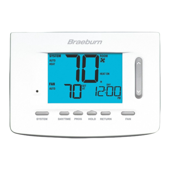
Lock Mode Indicator ....Indicates if the thermostat is locked SpeedBar ........ I ncreases or decreases settings (time, temperature, etc.) ® System Status Indicator ..... D isplays information about the status of the system Outdoor Temperature .... I f a Braeburn ® outdoor sensor was connected you can view the outdoor Day of the Week ...... D isplays the current day of the week temperature by pressing the PROG and HOLD buttons at the same time. Program Event Indicator.... D isplays the program event Installer Clear Button.... -
Page 6: Installer Settings
Mode (ARM™) Enables Adaptive (early) Recovery mode DAY/TIME I SENS I SENS 19 Indoor Remote Sensor Temperature is sensed from thermostat only. Control* [note 9] E SENS Temperature is sensed from remote sensor only. A SENS Temperature is combined with the thermostat and NOTE: Shaded areas below do not apply to the 5020. t he remote sensor. 2 LOCK 2 LOCK No. Installer Setting Factory Setting Comments 20 Lockout Security Level If locked – Complete lockout is enabled Default Options 1 LOCK... - Page 7 Detailed Explanation of Installer Settings (also see NOTES above): installation, the thermostat will automatically detect the sensor. When an indoor sensor is detected, you may select between thermostat only (I SENS), remote sensor only (E SENS) or combining the thermostat and the Profile – Selects a residential (RES) or commercial (COMM) profile. If residential is selected, 4 programming remote sensor (A SENS). NOTE: This option does not apply to a Braeburn outdoor sensor. When an outdoor events per day are available. If commercial is selected, 2 event, 7 day programming is available. sensor is connected the thermostat automatically recognizes it and no further configuration is necessary. Programming Mode [note 1] – Selects the programming mode, either full 7 day or 5-2 day (weekday/...
-
Page 8: System Testing
LIMITED WARRANT Y • Do not select the COOL mode of operation if the outside temperature is below 50º F (10º C). This could · Visit us online: www.braeburnonline.com/warranty possibly damage the controlled cooling system and may cause personal injury. · Phone us: 866.268.5599 · Write us: Braeburn Systems LLC • This thermostat includes an automatic compressor protection feature to avoid potential damage to the 2215 Cornell Avenue compressor from short cycling. When testing the system, make sure to take this delay into account. Montgomery, IL 60538 NOTE: The compressor delay can be bypassed by pressing the reset button on the front of the thermostat. All user settings will be returned to factory default, however all Installer settings will remain as originally Store this manual for future reference.
Need help?
Do you have a question about the 5020 and is the answer not in the manual?
Questions and answers