Konica Minolta bizhub C360 Installation Manual
Hide thumbs
Also See for bizhub C360:
- Service manual (1150 pages) ,
- User manual (402 pages) ,
- Installation manual (25 pages)
Table of Contents
Advertisement
/
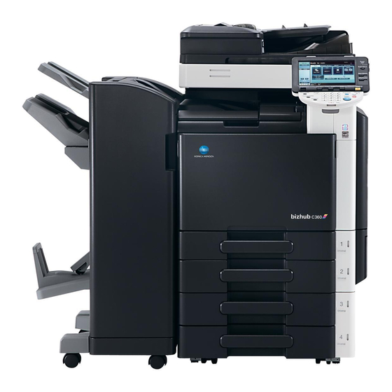
INSTALLATION MANUAL
<Important>
Be sure to correctly follow the procedures in order as explained in this Installation Manual.
If you do not follow the procedure in order, the image trouble may occur.
I. Outline of installation procedures
PC-107
PC-207
PC-408
AU-101
WT-506
AU-102
Machine
*2
WT-507
AU-201
KH-101
SP-501
DF-617
Electron system options
JS-603
PK-517
FS-529
FS-527
SD-509
When installing the machine and associated options as a system, follow the order shown on the upper.
Note:
• For the detailed installation procedures for each
option, follow the instructions given in the corre-
sponding installation manual and perform the
procedures correctly. (Optional devices must be
installed after completing the main body instal-
lation.)
• When placing the machine on the floor, make
sure to use the paper feed cabinet or the desk
to secure the performance and the quality of
the product.
• To use this machine, install the reverse auto-
matic document feeder or the original cover.
Even if you do not install the original cover, be
sure to install the hinge covers furnished with
the original cover.
• Once the Power Switch is turned ON, do not
turn OFF it until the installation work has been
completed.
• Lifting the machine in an awkward position or
transporting it in a poorly balanced position
/
Applied Machines:
/
/
DK-507
✱ Electron system options
*1
*1
EK-604
EK-605
MK-713
*1
UK-203
*3
VI-505
OC-509
*4
HD-515
MK-720
FK-502
SC-507
JS-505
*3
IC-412
*1
: No particular order in installation procedures.
*2
: Varies depending on the applicable marketing area.
*3
: Unable to be installed in C220.
*4
: For C220 only.
could result in personal injury. When transport-
ing the machine, assign an adequate number of
persons to the job and ensure that each person
can take a good position of not being exces-
sively loaded.
(mass: approx. 98 kg (216-1/16 lb))
A0ED-9601-00
II. Installation space (unit: mm (inch))
bizhub C360 + DF-617 + PC-207 + FS-527
SD-509 + MK-713
658
(25-7/8)
321
(12-5/8)
III. Pre-installation check items
1. Select a level and stable place for installing the
machine.
2. Be sure to use a power source of the voltage and
frequency indicated in the product specifications.
Ensure that the current carrying capacity of the
power outlet is at least equal to the current listed
in the product specifications.
3. Power the machine directly from a dedicated
power outlet. (Do not use an extension cord.)
4. Do not plug or unplug the power cord with wet or
dirty hands, otherwise you may get an electric
shock.
5. Avoid a hot and humid environment, or a place
exposed to direct sunlight.
6. Avoid a dusty location, or a place near volatile
and flammable substances.
7. Avoid a poorly ventilated place.
A0EDIXC041DA
E-1
IV. Accessory parts
No.
1. User's guide holder
1909
(75-3/16)
2. Quick guide
(Copy/Fax/Scan/Box operations) *
991
260
(39)
(10-1/4)
3. Installation manual
4. User's guide CD
5. CD-ROM
6. Paper size label
7. Label (Legal restrictions on copying) *
8. Label (Super G3 label)
9. Cap A (Black)
10. Cap B (White)
11. Power cord
12. Power cord instruction *
13. Cord clamp
1463.2
14. Waste toner box
(57-5/8)
15. Control panel
1092.2
(43)
16. Screw (3
17. Spacer
18. Panel pen
* Varies depending on the applicable marketing
area.
Note:
Keep the label (Super G3 label) at hand. It is nec-
essary for mounting the FAX Kit.
After unpacking, be sure to get rid of the
A0EDIXC042DA
packaging materials and keep them out of
the reach of children.
Putting the head in the plastic bag
involves danger of suffocation.
Note:
This manual provides the illustrations of the acces-
sory parts and machine that may be slightly differ-
ent in shape from yours. In that case, instead of
the illustrations, use the appearance of your
machine to follow the installation procedure. This
does not cause any significant change or problem
with the procedure.
Name
Q'ty
1
1
1 set
1
1 set
1
1
1
2
2
1
1
1
1
1
×
6 mm)
1
1
1
Advertisement
Table of Contents

Related Manuals for Konica Minolta bizhub C360


Summary of Contents for Konica Minolta bizhub C360
-
Page 1: Installation Manual
II. Installation space (unit: mm (inch)) IV. Accessory parts bizhub C360 + DF-617 + PC-207 + FS-527 INSTALLATION MANUAL Name Q’ty SD-509 + MK-713 1. User’s guide holder 1909 (75-3/16) 2. Quick guide Applied Machines: (Copy/Fax/Scan/Box operations) * (25-7/8) (39) (10-1/4) 3. - Page 2 V. Removing the machine VI. Removing protective tape, packing and 2. Open the right door and remove the protective 4. Install the furnished control panel. sheet and packaging materials. Note: other shipping materials / Installing the 1. Unpack and remove the machine package. Note: Insert the hook of the control panel into the posi- 2.
- Page 3 7. Remove the protective sheet. 10. Open the front door and remove the protective 13. Slightly slide the drum unit (K) out and remove 2. Insert the toner cartridge into the machine. tape. the protective tape. Note: • Make sure that the color is same between inserting port and the toner cartridge.
- Page 4 VIII. Installing the waste toner box IX. Mounting the accessory parts XI. Installing the set guide for banner 2. Connect the power cord. paper 1. Remove the protective tape from the furnished 1. Attach the cap A and B furnished with the waste toner box.
- Page 5 XIII. Toner supply 4. Touch “OK.” × <If A3 or Ledger paper is set in step 1> 12. Touch “Copy”, select “A3 ”, and 5. Touch “Exit” on the Service Mode screen. 6. Touch “Print”, select “A3 × ”, and press the start key.
- Page 6 XVII. Date/Time setting XIX. Serial number input <If A4 or Letter paper is set in step 1> 12. Touch “Copy”, select “A4 ½×11 ”, and press the start key. 6. Touch “Print”, select “A4 ½×11 ”, and 1. Make sure that the Service Mode screen is dis- Note: A test pattern will then be produced on the two press the start key.
- Page 7 XXII. Affixing the paper size label XXIV. Adjusting registration of paper 10. If the measured width A falls outside the speci- 9. Measure width A of the test pattern on the back- fied range, enter the correction value using the side of the test print produced and check that it source options Affix the paper size label.
- Page 8 OC-509 XXVI. Connecting cables 3. Connect the networking equipment (HUB) using Original Cover the network cable. 1. Remove the knockout from the cover located on INSTALLATION MANUAL Note: the right side of the machine with nippers as The following shows the recommended network shown in the illustration.
Need help?
Do you have a question about the bizhub C360 and is the answer not in the manual?
Questions and answers